EaseWatcher: Smart Surveillance Made Easy

EaseWatcher is a comprehensive DIY smart surveillance system that empowers users to create a robust and customizable security solution for their homes or businesses. This innovative system combines cutting-edge technology with ease of use, allowing individuals to monitor and protect their properties with confidence.

With EaseWatcher, users can effortlessly connect multiple cameras, triggers, and alarm channels to create a seamless surveillance experience. The system’s modular design enables users to add or remove components as needed, making it an ideal solution for a wide range of applications.

EaseWatcher’s advanced features include:

  • Real-time video streaming and recording
  • Motion detection and alert notifications
  • Customizable alarm channels for instant notifications
  • Support for multiple camera types and protocols
  • Cloud-based storage for secure and convenient access

By leveraging the power of EaseWatcher, users can enjoy peace of mind knowing that their properties are protected and monitored around the clock. Whether you’re a homeowner looking to safeguard your family and assets or a business owner seeking to enhance security…

Monitoring Network Traffic: Bluetooth Network Monitor

You can read about the newer version of the Bluetooth network monitor here, but I suggest you continue reading this article.

I often encounter slow download speeds or online gaming lag, and every time I have to log in to my router’s web page or via SSH to check if it’s because of others in my household downloading/uploading, unstable network connections, or simply a server issue. It’s really frustrating. So, I decided to create a device that displays network statistics in real-time, making it more convenient to monitor network traffic.

The monitor consists of an ATmega328P @ 20MHz, a 160×128 1.8-inch color LCD, and a Bluetooth module, powered by 5V USB. It has a button that long-presses to adjust the LCD brightness and short-presses to switch display modes. Since it’s powered by USB, I added support for V-USB.

Enclosure Design:

  • Uses an A8 paper display holder
  • Removes the back clip part
  • Adds rubber feet

Monitor Modes:

  • Display Mode 1:
    • Downlink sync
    • Uplink sync
    • Download rate
    • Upload rate
    • 25-second historical chart
    • Flat
    • Packet loss
    • WAN IP
    • Time
    • Email notification
  • Display Mode 2:
    • Download rate
    • Upload rate
    • 40-second large historical chart

Future Plans:

  • Add more

Bluetooth Module Communication: Configuration and Testing

A Simple Way to Make Your Project Wireless with Serial Bluetooth Modules

Using serial Bluetooth modules is a straightforward way to make your project wireless, as they can transparently transmit standard serial data to another connected Bluetooth module, without requiring additional code.

Adding Bluetooth to Your Project for Mobile Control

To add Bluetooth to your project for mobile control, simply insert a slave module and connect to it via your phone. However, getting two modules to communicate with each other requires understanding some basic concepts.

How Bluetooth Modules Work

Bluetooth modules work in slave and master modes. Slave modules cannot initiate connections with other Bluetooth devices, but can accept connections. Master devices can be set to master or slave mode, and in master mode, they can initiate connections with other devices. Be sure not to make the mistake of buying two slave devices! You need two master devices or one master and one slave device.

What to Note When Buying Bluetooth Modules

Sometimes, eBay sellers may not provide much information about their modules. To determine whether a module is a slave or master device, be sure to check the following:…

Introduction to nRF905 Wireless Transceiver IC Library

The nRF905 is a wireless transceiver IC similar to the nRF24L01, but with a working frequency of 433/898/915MHz, offering a longer range and more IO pins. Although the data rate of nRF905 is only 50Kbps, lower than the 2Mbps of nRF24L01, this library provides considerable flexibility.

The library supports the use of interrupts and allows for the option of connecting two modules, as their status can also be accessed through the IC’s status registers. Additionally, the library supports basic collision avoidance mechanisms.

NOTE: v3.0.0 of the library was released on 12th September 2017, the default CD pin has changed and the AM pin is now used by the library.

Download

Arduino: [HERE] and [Documentation] (or use the Arduino library manager and search for “nrf905”)

AVR (non-Arduino): [HERE] and [Documentation]

nRF905ATmega48/88/168/328Arduino UnoDescription
VCC3.3V3.3VPower (3.3V)
CED7 (13)7Standby – High = TX/RX mode, Low = standby
TXEB1 (15)9TX or RX mode – High = TX, Low = RX
PWRB0 (14)8Power-up – High = on, Low = off
CDD4 (6)4Carrier detect – High when a signal is detected, for collision

About LCD Image Viewer

This is a rapid project I’ve worked on, using a 1.8-inch color LCD display from Ebay. The microcontroller code is very simple, initializing the display and then waiting for serial data to be sent directly to the screen. The host program handles image processing, opening the image and resizing it, displaying it in a preview window, and converting it to 12, 16, or 18-bit color during upload.

Additionally, I’ve added various interactive features to the preview window, including image rotation, scaling, and movement, making the project more practical and interesting.

Setup is wired as follows –

LCD pinArduino Uno pin
VCC5V
BKLGND
RESET**RESET
RS9
MISO*12
MOSI11
SCLK13
LCD CS10
SD_CS*4
GNDGND

* These are only needed if you’re using the SD slot on the back of the LCD
** Connect RESET to make the LCD reset along with the controller, if you don’t need that then leave disconnected or connected to 5V

Downloads

LATESTLCDImageViewer_20121026.zip (2.07 MB)
Host program and source (C# .NET), Arduino sketch code, Arduino LCD library and normal AVR C code (you can probably get it working on an ATtiny25)
MD5: DD6AC95ABD72318BFEA2B04F30F058BC

This article discusses three development…

AVR USB RGB LED Controller Project

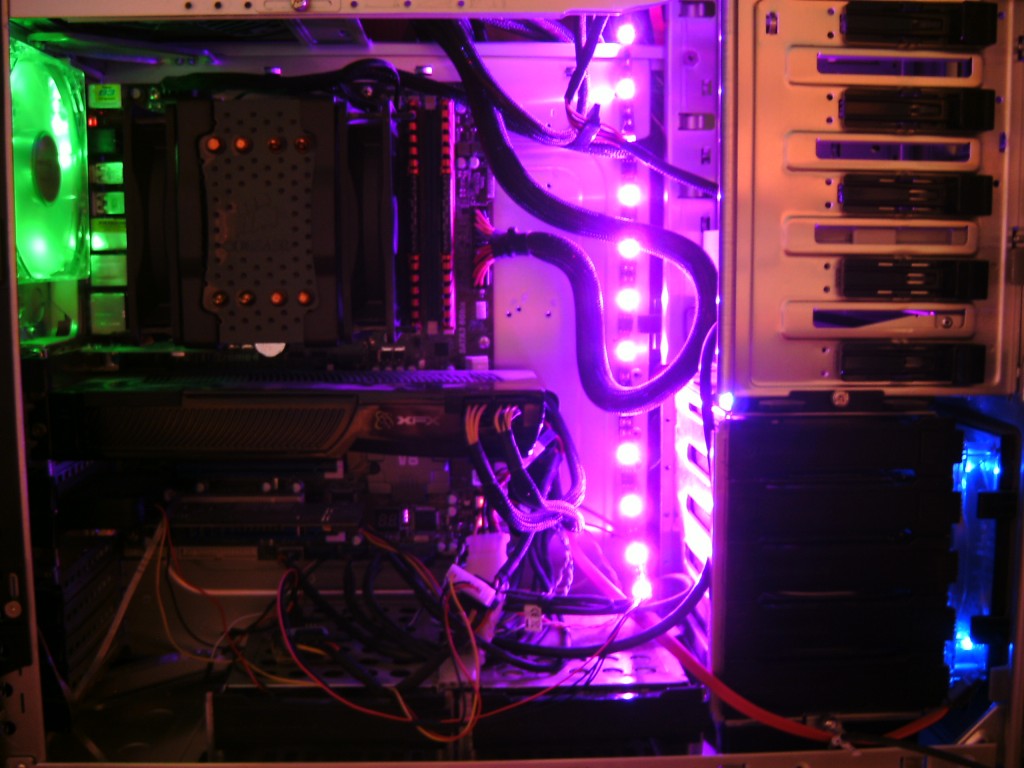
This project uses an ATtiny45 microcontroller to control an RGB LED strip based on CPU usage. It’s a cool-looking project that uses the V-USB library to communicate with the PC without needing a USB-to-TTL serial converter.

AVR USB RGB LED Controller 

Hardware

The project uses an ATtiny45 microcontroller and ZVN4306A MOSFETs to control the RGB LED strip, with each color consuming only about 90mA of current. The MOSFETs are more efficient and produce less heat, allowing for more current to flow.

Firmware

The firmware uses Timer 0 and Timer 1 to implement PWM control of the LED strip at 500Hz, and Timer 0 also keeps track of milliseconds for idle timeout. The EEPROM saves the delay setting every 4 seconds, which helps extend the lifespan of the EEPROM and the LED color transition time. When the idle timeout is reached, the LED strip starts cycling through blue, green, and red colors until it receives USB data again.

Host Program

The host program is written in C and is compatible with Windows and Linux. It can set the LED color based on CPU usage or set a single static color. The setting is saved to the EEPROM, so it will restore to the previous setting when the PC is restarted.

Alternative

IR Interferer Circuit Based on 555 Timer: Notes on Power Supply Voltage and Transistor Selection

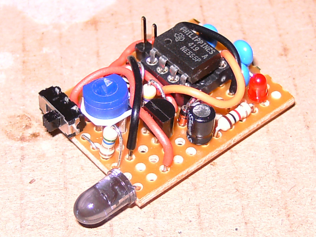
I built a simple circuit based on a 555 timer to interfere with infrared (IR) communications such as TV remote controls. When I first made it (October 2011), the circuit was unreliable in interfering with IR signals and eventually stopped working. It wasn’t until I recently bought a mini DSO that I discovered the circuit required at least 6.5V to reach the 38KHz frequency, while the 9V battery I was using was running out of power and couldn’t provide enough energy to reach 38KHz. After connecting it to a clean 9V power source and adjusting it to 38KHz with the help of the mini DSO, the interferer finally worked perfectly.

It’s worth noting that the transistor, 470R and 5R6 resistors, and 1N4148 diode form a constant current source of approximately 125mA to drive the IR LED. This will make the transistor quite hot. With a 9V power supply voltage and an LED Vf of 1.6V, the voltage drop across the transistor will be 6.8Vce, producing 850mW of heat at 125mA. This is actually higher than the rated 630mW of the 2N4401 transistor I used, so please make sure to choose the correct transistor to avoid problems.

[Schematic source (50 – 555 Projects on Talking Electronics)]

Microcontroller PWM Controller: A Design Based on ATtiny25 and MOSFET

I recently designed a PWM controller based on a microcontroller and MOSFET, which can control high-current loads. It’s a bit like a PWM controller based on a 555 timer, but now using a microcontroller and MOSFET instead of a 555 IC and transistor.

I made two versions, one with acceleration and deceleration switches, and another with a potentiometer. The controller uses an ATtiny25 microcontroller, running at 31.25KHz (8MHz internal RC/256 prescaler), powered by 3.3V. I used an STP36NF06L MOSFET, with a maximum 0.045Rds and 2.5Vgs, which is suitable for 3.3V power supply. The MOSFET produces only ~180mW of heat at 2A, which doesn’t require a heat sink.

In the circuit diagram, if using a 5V power supply, R1 should be changed from 100R to 150R to keep the current below 40mA. Zener diodes D1 and D2 are used for ESD protection, requiring a voltage rating above the uC power supply voltage and below the maximum gate voltage of the MOSFET. The STP36NF06L MOSFET can easily switch ~8A, but requires some heat sinks. The potentiometer selection also needs to consider the microcontroller ADC reading and current consumption.

Update – July 10, 2013

I recently designed a new …

From Arduino to AVR Microcontrollers: My Electronic Journey

I’ve been following Arduino and finally got my hands on an Uno and a 16×2 character LCD with RGB backlight. This new electronic world is exciting me. For years, I’ve been interested in digital control devices like LCDs, wondering how to use them, but was always blocked by the complexity of microcontrollers. However, using Arduino’s LCD library made it easy to connect the LCD, and I quickly made a stereo audio VU meter and a basic FFT spectrum analyzer.

Next, I started exploring wireless technology. I bought NRF24L01 wireless modules, a USBASP AVR programmer, a USB to UART converter, and an ATMega168 microcontroller from Ebay. Using the Mirf library, I successfully made one controller change the LCD backlight color of another controller.

After getting used to the Arduino IDE, I wanted to dive deeper into how the code truly controls the chip. So, I downloaded Atmel Studio 6, the ATMega168 chip datasheet, and followed tutorials on avrfreaks.net to learn the basics of AVR microcontrollers, starting from timers and interrupts. Now, I’ve grasped the basics of AVR microcontrollers and have many project ideas involving AVR uCs.

EaseHome: Unlock the Future of Smart Home Automation

EaseHome is a revolutionary smart home chatbot that lets you control and monitor your home with ease. Using natural language processing and machine learning, EaseHome understands your voice commands and responds accordingly, making it easy to manage your home’s temperature, lighting, security, and more. With EaseHome, you can experience the future of smart home automation today.

Getting Started

EaseHome Tutorial

EaseHome: Unlock the Future of Smart Home Automation

Welcome to EaseHome: A Smart Home Chatbot Tutorial

Imagine being able to converse with your home, effortlessly asking questions like “What’s the current temperature?” or “Are all doors locked?” and even controlling your home’s settings with simple voice commands like “Set the kitchen temperature to 19°C!” This futuristic vision, inspired by movies like “Minority Report,” is now within reach. In this tutorial, we’ll explore how to integrate a cutting-edge text recognition system into a smart home system using the Microsoft Bot Framework and Language Understanding Intelligent Service (LUIS).

The Dream of a Smart Home