Custom Laptop Power Supply Project

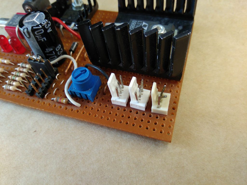
Your desktop power supply has been running for many years, still maintaining good performance, which is indeed a remarkable feat! However, the output power connector selection has some shortcomings, with the 3-pin header type connector not being suitable for this power output, which can easily lead to cooling issues.

It’s time to upgrade your power supply now! Consider using a better output power connector, such as MOLEX or SATA interfaces, which are more reliable and universal. Additionally, improving the heat dissipation design, such as adding heat sinks or improving the heat dissipation ventilation system, will also help to ensure stable operation of the power supply.

Furthermore, using more modern power management technologies, such as DC-DC converters or switching power modules, can improve the efficiency and reliability of the power supply. In summary, it’s time to upgrade your power supply to make it more stable, reliable, and efficient!

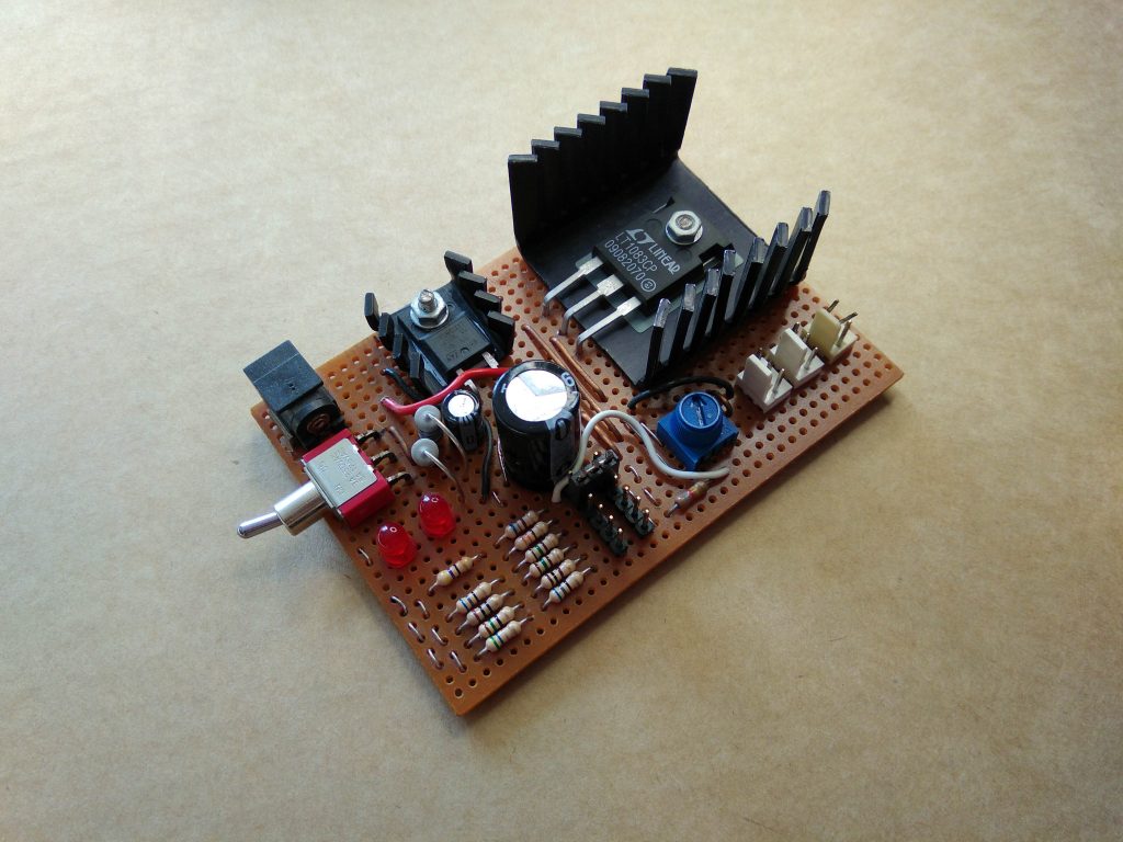
The old power supply
Messed up output connectors

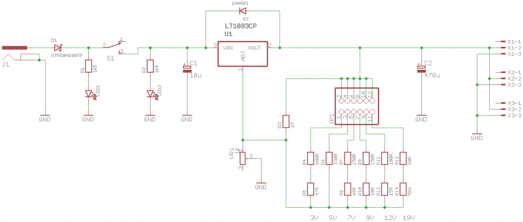
Old regulator schematic

A true desktop power supply typically comes with features such as adjustable current limiting and a display for voltage and current. However,…

AVR-GCC 14.1.0 for Windows released: supports 32-bit and 64-bit systems

You plan to upload a version of AVR-GCC that is compatible with both 32-bit and 64-bit Windows, including Binutils, AVR-LibC, AVRDUDE, Make, and GDB. This means you will provide a complete development toolchain, making it convenient for Windows users to develop AVR microcontroller projects.

You also mention that, except for AVRDUDE, all binary files are built from source code using MinGW on a Debian virtual machine. This ensures the reliability and consistency of the binary files.

Providing both 32-bit and 64-bit Windows binary files is also convenient for users to choose the suitable version. Moreover, you will provide a bash script that allows users to easily build AVR-GCC, AVR-Binutils, AVR-LibC, and AVR-GDB from source code. This is particularly useful for users who need to customize or optimize the toolchain.

Overall, your upload will provide a convenient, reliable, and customizable AVR microcontroller development toolchain for Windows users.

Included tools

ToolVersion
GCC14.1.0
Binutils2.42
AVR-LibC2.2.0
GDB14.2
AVRDUDE7.2 (Not included in Linux release)
Make4.2.1 (Not included in Linux release)

Downloads

LATESTavr-gcc-14.1.0-x64-windows.zip (141

aspberry Pi 4 PCIe Bridge Chip Solution

After seeing Thomasz Mloduchowski and Colin Riley‘s successful project of bridging the PCIe bus to a USB 3.0 port on the Raspberry Pi 4, I felt extremely motivated! After reading the comments on hack-a-day, I decided to give it a try myself!

So, I designed a PCIe bridge “chip” that can simply replace the VL805 USB 3.0 controller chip on the Pi, allowing access to the PCIe bus on the USB 3.0 port. However, this also means that all USB functionality on the Pi will be lost. If you encounter network issues and need to connect a keyboard, this might be a bit troublesome.

Fortunately, there’s a solution. The USB-C power connector appears to be able to function as a USB host, as long as 5V power is provided through the GPIO header, allowing a keyboard to be connected. This is a very practical solution that can meet our needs.

The bridge “chip” is a 0.8mm thick PCB from OSHPark with copper pads in the same locations as a real VL805 QFN68 IC package, then traces connecting the PCIe pads to the USB pads that connect to the upper USB 3.0 port. RESET, WAKE and a few other signals were also connected to the lower USB 3.0 port.

PCIe SignalDirectionUSB Signal
REFCLK+Host -> DeviceD-

Remote Mail Monitoring: Keep an Eye on Your Mailbox

I want to create a system that can notify me when the mailman delivers a package to my mailbox. Considering that my mailbox is located in the central hallway area, the mailman’s visit time is unpredictable, and I don’t have a window facing the road, so I can’t see the mailman’s arrival.

Here are some suggestions:

Install a smart mailbox: I can install a smart mailbox equipped with sensors and Wi-Fi connectivity, which will send a notification to my phone or email when the mailman delivers a package.
Use a motion detector: I can install a motion detector near the mailbox, which will detect the mailman’s movement and send a notification to my phone.
Mailbox camera: I can install a small camera near the mailbox, which will take a photo when the mailman delivers a package and send it to my phone.
Mailman signing system: I can work with my neighbors or building administrators to establish a mailman signing system, which requires the mailman to sign for confirmation when delivering a package, and then I will receive a corresponding notification.

These methods can help me receive notifications when the mailman delivers a package, solving my problem.

The mailboxes…

EaseRobot – A Cutting-Edge Autonomous Robot

Welcome to EaseRobot, a cutting-edge autonomous robot designed to revolutionize home automation. This innovative DIY robotics project aims to create a sophisticated house-bot that can navigate and interact with its environment. In this series, we’ll delve into the project’s details, starting with the concept, hardware selection, and initial software development.

Inspired by the possibilities of modern robotics, EaseRobot is built around a Raspberry Pi 3, Model B, leveraging its processing power and versatility. By harnessing the capabilities of the Robot Operating System (ROS) and Raspberry Pi, we can focus on developing the robot’s features rather than building a custom processor board from scratch.

EaseRobot is designed to perform various tasks, including facial recognition, speech synthesis, and autonomous locomotion. Our robot will be equipped with a 7″ touchscreen display and a camera module, enabling it to interact with users and navigate its surroundings. With ROS, we can develop and test nodes for the system, simulate the robot’s behavior, and refine our code.

In this project, we’ll explore various “missions”…

Rolling in Miniature: A Compact Electronic Die

Introducing a tiny, minimalist electronic die project that packs a punch! With just 7 LEDs, an ATtiny25V, a CR1616 coin cell battery, and some passive components, this device is incredibly compact, measuring only 18mm x 18mm in size, 4.9mm in thickness, and weighing a mere 2.1 grams.

https://youtube.com/watch?v=E05Uq4TWpRk

This tiny electronic die features a single button, the roll button, which triggers the die to cycle through numbers 1 to 6 when held down. When the button is released, the scrolling slows down until the final change, at which point it switches to a randomly generated number using the XORShift random number generator algorithm. The XORShift algorithm is lightning-fast, compact in code, and maintains excellent randomness, making it a perfect fit for this project. The final value flashes several times before the die powers off after a few seconds.

Battery Life

The dice is powered by a CR1616 coin cell with a capacity of around 50-60mAh.

Current draw:

StateCurrent @ 3V
Off<0.1uA
Active2.4mA (average)

Some battery life calculations:

Number of rolls24,000 @ 3 seconds per roll (a quick press of the roll button)
Total duration20 hours

Rolling the dice 20 times…

Smart USB Power Switch and Filter

The agony of constantly unplugging and replugging the USB cable every 5 seconds to power your project! It’s even more infuriating when you’ve exhausted all the front USB ports and have to awkwardly reach around to the back of the PC. This project seeks to alleviate this frustration by incorporating a simple button to toggle the USB power on and off, along with some additional convenient features.

While a USB hub with individual port power switches would be a straightforward solution, this project takes a more innovative approach. By utilizing the MIC2545A high-side switch with 3A adjustable current limiting and soft-start functionality, this design offers a more sophisticated solution. The switch is controlled by an ATtiny25V microcontroller, allowing for customized control of the switch’s behavior in short-circuit conditions. Normally, the MIC2545A would limit the current, but with the microcontroller, it can immediately shut off the switch upon detecting a short circuit, or use a small delay or low-pass filter to prevent tripping due to instantaneous current spikes. Additionally, ESD protection is added to the data and power lines, a noise filter…

Custom Rev Limiter Warning System and Gear Position Indicator

I’ve had my Toyota GT86 for a while, and I absolutely loved its built-in rev limiter warning and the thrill of flooring it until an elderly lady cancelled my insurance. However, I was fortunate enough to drive a BMW 430d M Sport courtesy of my insurance company for a few months. Currently, I’m behind the wheel of a 2006 Honda Civic Type-S GT hatchback, and I’m really missing that warning (and the rest of the 86’s goodies).

https://youtube.com/watch?v=pzZLg0P67D4

By leveraging Arduino and an affordable MCP2515 module, I successfully sniffed the communication between the ELM327 diagnostic tool and my Civic’s OBD-II port. I discovered that the CAN bus operates at a speed of 500Kbps, transmitting a multitude of standard 11-bit ID CAN messages. By sending the “010c” command to the ELM327 to request engine RPM data, I observed it sending extended 29-bit CAN messages with an ID of 0x18DB33F1, followed by a response ID of 0x18DAF110. (I won’t delve into the intricacies of OBD-II protocol’s physical and functional addressing here, but searching for these two hex numbers online will yield some fascinating results.) Excellent!…

Si4463 Wireless Library: A Wireless Communication Solution for AVR and Arduino

This is a library for the Silicon Labs Si4463 wireless IC, which has been used in (or will be used in) some of my projects. The Si4463 offers various configuration options, including modulation, data packet format, and CRC algorithm, and can output up to +20dBm (100mW) of power. Additionally, the Si4463 is also used in many pre-made modules, such as the HopeRF RFM26W and the Dorji_Com DRF4463F. The entire Si446x transceiver series should also be compatible with this library.

This library allows users to configure the chip to send and receive variable-length data packets (up to 128 bytes) and trigger callback functions when events occur (such as receiving new data packets and completing data packet transmission). These callback functions run directly from the interrupt routine, making the program’s response to events much faster than with polling libraries.

Download from GitHub
Documentation

Pinout

Si4463ATmega328Arduino UnoArduino MegaDescription
VCC3.3V3.3V3.3VPower (3.3V)
GPIO0
GPIO1
SDOB4 (18)1250SPI MISO
SDIB3 (17)1151SPI MOSI
SCLKB5 (19)1352SPI SCK
NSELB2 (16)1010

Hacking RAM SPD Data: A Step-by-Step Guide


I recently purchased some low-power Mini-ITX motherboards, including the Gigabyte GA-N3050N-D3H and Biostar N3050NH. These motherboards use SO-DIMM DDR3 RAM, commonly found in laptops.

Although these two motherboards are very similar, the Gigabyte motherboard lacks some BIOS features and settings compared to the Biostar motherboard. One of the missing features is the inability to set the RAM frequency. I want to run the RAM at a minimum frequency of 800MHz, but the Gigabyte motherboard runs it at the normal frequency of 1600MHz. This means that the Biostar motherboard can reduce idle power consumption by about 0.12W, or around 2%, with just a simple switch.

To solve this problem, I need to modify the RAM’s Serial Presence Detect (SPD) data. The SPD data is a set of configuration parameters stored in a small EEPROM chip, which the BIOS reads during boot-up. Fortunately, the SPD EEPROM communicates using SMBus, which is largely compatible with I2C on Arduino.

The SPD EEPROM

Modifying the RAM’s SPD data is not a new concept, and there are already many tools and programs available online that can perform SPD operations. However, the software and hardware compatibility…