I’ve had my Toyota GT86 for a while, and I absolutely loved its built-in rev limiter warning and the thrill of flooring it until an elderly lady cancelled my insurance. However, I was fortunate enough to drive a BMW 430d M Sport courtesy of my insurance company for a few months. Currently, I’m behind the wheel of a 2006 Honda Civic Type-S GT hatchback, and I’m really missing that warning (and the rest of the 86’s goodies).
By leveraging Arduino and an affordable MCP2515 module, I successfully sniffed the communication between the ELM327 diagnostic tool and my Civic’s OBD-II port. I discovered that the CAN bus operates at a speed of 500Kbps, transmitting a multitude of standard 11-bit ID CAN messages. By sending the “010c” command to the ELM327 to request engine RPM data, I observed it sending extended 29-bit CAN messages with an ID of 0x18DB33F1, followed by a response ID of 0x18DAF110. (I won’t delve into the intricacies of OBD-II protocol’s physical and functional addressing here, but searching for these two hex numbers online will yield some fascinating results.) Excellent! This is all the information I need to kick-start my project.
Sample capture output
Standard ID: 0x3F8       DLC: 8  Data: 0x00 0x00 0x00 0x00 0x02 0x20 0x19 0x44
Standard ID: 0x164       DLC: 8  Data: 0x04 0x00 0x00 0x38 0x7B 0x00 0x00 0x84
Standard ID: 0x0D0       DLC: 7  Data: 0x00 0x00 0x00 0x00 0x00 0x00 0x29
Extended ID: 0x18DB33F1  DLC: 8  Data: 0x02 0x01 0x0C 0x00 0x00 0x00 0x00 0x00
Extended ID: 0x18DAF110  DLC: 8  Data: 0x04 0x41 0x0C 0x0B 0xE4 0x55 0x55 0x55
Standard ID: 0x13F       DLC: 8  Data: 0x01 0x2E 0x01 0x22 0x00 0x00 0x00 0x0F
Standard ID: 0x0D0       DLC: 7  Data: 0x00 0x00 0x00 0x00 0x00 0x00 0x38
Standard ID: 0x294       DLC: 8  Data: 0x00 0x16 0x00 0x02 0x8D 0x52 0x00 0x04
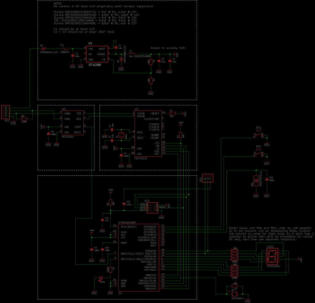
The rev alarm plugs into the vehicles OBD-II port, and contains an RT6200 buck regulator to drop the cars 12V down to around 5V, which is then used to power the ATmega328P microcontroller, MCP2515 CAN controller and MCP2561 CAN transceiver.


Here’s the implementation of the custom rev limiter warning system using the Arduino platform and the MCP2515 library
Setting Up the Device
To set up the device, I wrote code to:
- Increase the engine RPM to the desired level and press the right-side button to set the warning trigger point.
- Press the left-side button to cycle through the display modes on the 7-segment display, which can show the selected gear, the RPM closest to 1000, or nothing at all.
- Automatically adjust the display brightness using an LDR (Light Dependent Resistor).
Calculating Gear Position
Since the standard OBD PID doesn’t include a gear position parameter, I had to calculate it based on engine RPM, vehicle speed, wheel circumference, and gear ratio. Unfortunately, this means that every time the device is used on a different vehicle, the gear ratio and wheel circumference need to be reprogrammed. Additionally, any inaccuracies in the vehicle speed table, tire wear, and pressure may affect the calculation at low speeds (usually below 20MPH), which may require some fine-tuning. However, this can be easily done by adjusting the wheel circumference setting until the gear display stabilizes. For my Civic, I had to set the wheel circumference 4% lower.
Low Power Sleep Mode
Since the OBD port is always powered, even when the vehicle is turned off, I had to implement a low-power sleep function to prevent battery drain. Most electronic devices in the rev limiter warning system consume less than 70uA in sleep mode, but the voltage regulator consumes around 2.7mA, which is a bit higher than I’d like, but still low enough not to drain the battery over a long period.
The Arduino code and various other things are available on the GitHub repo.


