Projects

Smart USB Power Switch and Filter

The agony of constantly unplugging and replugging the USB cable every 5 seconds to power your project! It’s even more infuriating when you’ve exhausted all the front USB ports and have to awkwardly reach around to the back of the PC. This project seeks to alleviate this frustration by incorporating a simple button to toggle the USB power on and off, along with some additional convenient features.

While a USB hub with individual port power switches would be a straightforward solution, this project takes a more innovative approach. By utilizing the MIC2545A high-side switch with 3A adjustable current limiting and soft-start functionality, this design offers a more sophisticated solution. The switch is controlled by an ATtiny25V microcontroller, allowing for customized control of the switch’s behavior in short-circuit conditions. Normally, the MIC2545A would limit the current, but with the microcontroller, it can immediately shut off the switch upon detecting a short circuit, or use a small delay or low-pass filter to prevent tripping due to instantaneous current spikes. Additionally, ESD protection is added to the data and power lines, a noise filter…

Custom Rev Limiter Warning System and Gear Position Indicator

I’ve had my Toyota GT86 for a while, and I absolutely loved its built-in rev limiter warning and the thrill of flooring it until an elderly lady cancelled my insurance. However, I was fortunate enough to drive a BMW 430d M Sport courtesy of my insurance company for a few months. Currently, I’m behind the wheel of a 2006 Honda Civic Type-S GT hatchback, and I’m really missing that warning (and the rest of the 86’s goodies).

https://youtube.com/watch?v=pzZLg0P67D4

By leveraging Arduino and an affordable MCP2515 module, I successfully sniffed the communication between the ELM327 diagnostic tool and my Civic’s OBD-II port. I discovered that the CAN bus operates at a speed of 500Kbps, transmitting a multitude of standard 11-bit ID CAN messages. By sending the “010c” command to the ELM327 to request engine RPM data, I observed it sending extended 29-bit CAN messages with an ID of 0x18DB33F1, followed by a response ID of 0x18DAF110. (I won’t delve into the intricacies of OBD-II protocol’s physical and functional addressing here, but searching for these two hex numbers online will yield some fascinating results.) Excellent!…

Bluetooth Smart Monitoring System V2.0

This article only provides a sneak peek into the new features of the network monitor.I’d recommend having a look at the original post first.

  • New PCB design
    The new PCB is now an almost single board design, just a separate board for the USB connector. The old monitor had a small main board which connected to the LCD and Bluetooth modules. This new board has everything soldered straight on.
  • Revamped microcontroller code
    Refactored a lot of the microcontroller code, reduced RAM usage and improved performance a little bit.
  • New router program
    The router program is now completely written in C! Uses much less CPU time than the old shell script.
  • New host program
    Written in C# .NET and uses LibUsbDotNet. It’s still in early development, but at the moment allows uploading images (takes around 2.5 – 3 seconds to upload), drawing stuff (mouse click and drag) and controlling the display brightness.
  • Other new features
    New efficient binary protocol instead of a text protocol.
    Added a temperature sensor since there was a lot of room left on the PCB, however this turned out to be a bit useless for measuring the room temperature because of the heat dissipated by nearby parts, mainly

Low-Power Microcontroller Applications in Smartwatches

Introduction

The main motivation behind this project was to see how much hardware and software I could cram into a small, watch-like device. I chose an OLED display because it’s only 1.5mm thick, doesn’t require a backlight, and each pixel emits its own light, making it look really cool. Initially, I planned to use a 0.96-inch display, but it turned out to be too small to fit all the components I wanted. Increasing the size to 1.3 inches proved to be the perfect solution.

https://youtube.com/watch?v=KrUJlZK1ct0

Hardware

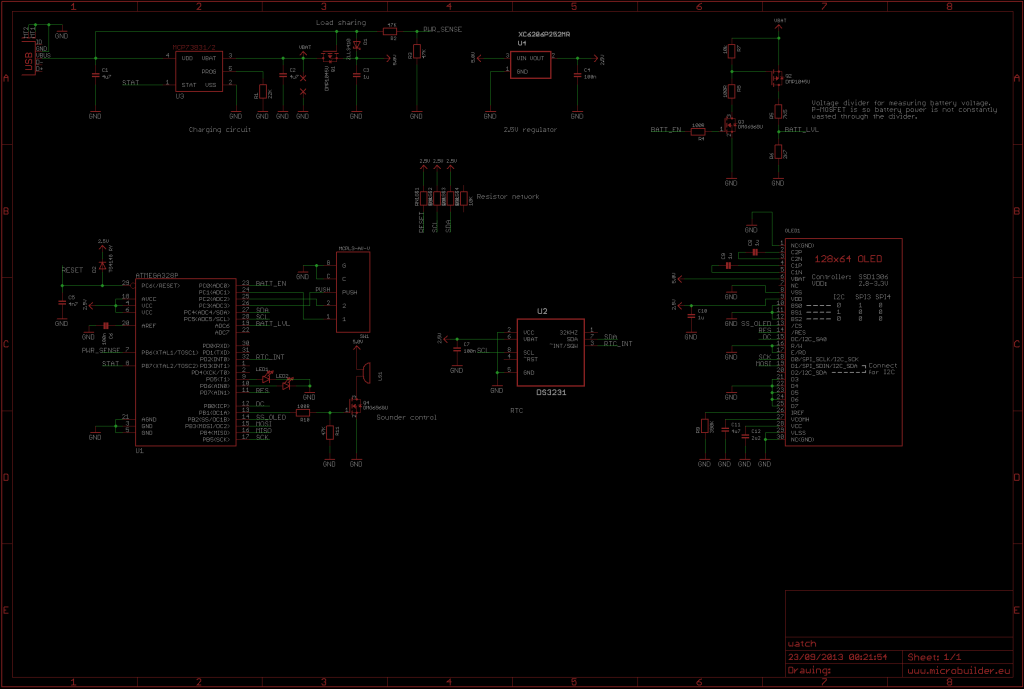
The hardware components of this watch include an Atmel ATmega328P microcontroller, a 2.5V voltage regulator, a Maxim DS3231M RTC, a 1.3-inch 128×64 monochrome OLED, 2 LEDs (red and green), a buzzer, a 3-route navigation switch, powered by a 150mAh LiPo battery, and charged via USB and 2 PCBs.

The microcontroller ATmega328P uses its internal 8MHz oscillator and runs at 2.5V. It consumes approximately 1.5mA in active mode and 100nA in sleep mode.

The DS3231M RTC is a high-precision clock chip with a small 8-pin package, including a built-in temperature-compensated MEMS resonator, with an accuracy of ±5ppm (±2 minutes 40 seconds per year). …

Monitoring Network Traffic: Bluetooth Network Monitor

You can read about the newer version of the Bluetooth network monitor here, but I suggest you continue reading this article.

I often encounter slow download speeds or online gaming lag, and every time I have to log in to my router’s web page or via SSH to check if it’s because of others in my household downloading/uploading, unstable network connections, or simply a server issue. It’s really frustrating. So, I decided to create a device that displays network statistics in real-time, making it more convenient to monitor network traffic.

The monitor consists of an ATmega328P @ 20MHz, a 160×128 1.8-inch color LCD, and a Bluetooth module, powered by 5V USB. It has a button that long-presses to adjust the LCD brightness and short-presses to switch display modes. Since it’s powered by USB, I added support for V-USB.

Enclosure Design:

  • Uses an A8 paper display holder
  • Removes the back clip part
  • Adds rubber feet

Monitor Modes:

  • Display Mode 1:
    • Downlink sync
    • Uplink sync
    • Download rate
    • Upload rate
    • 25-second historical chart
    • Flat
    • Packet loss
    • WAN IP
    • Time
    • Email notification
  • Display Mode 2:
    • Download rate
    • Upload rate
    • 40-second large historical chart

Future Plans:

  • Add more

AVR USB RGB LED Controller Project

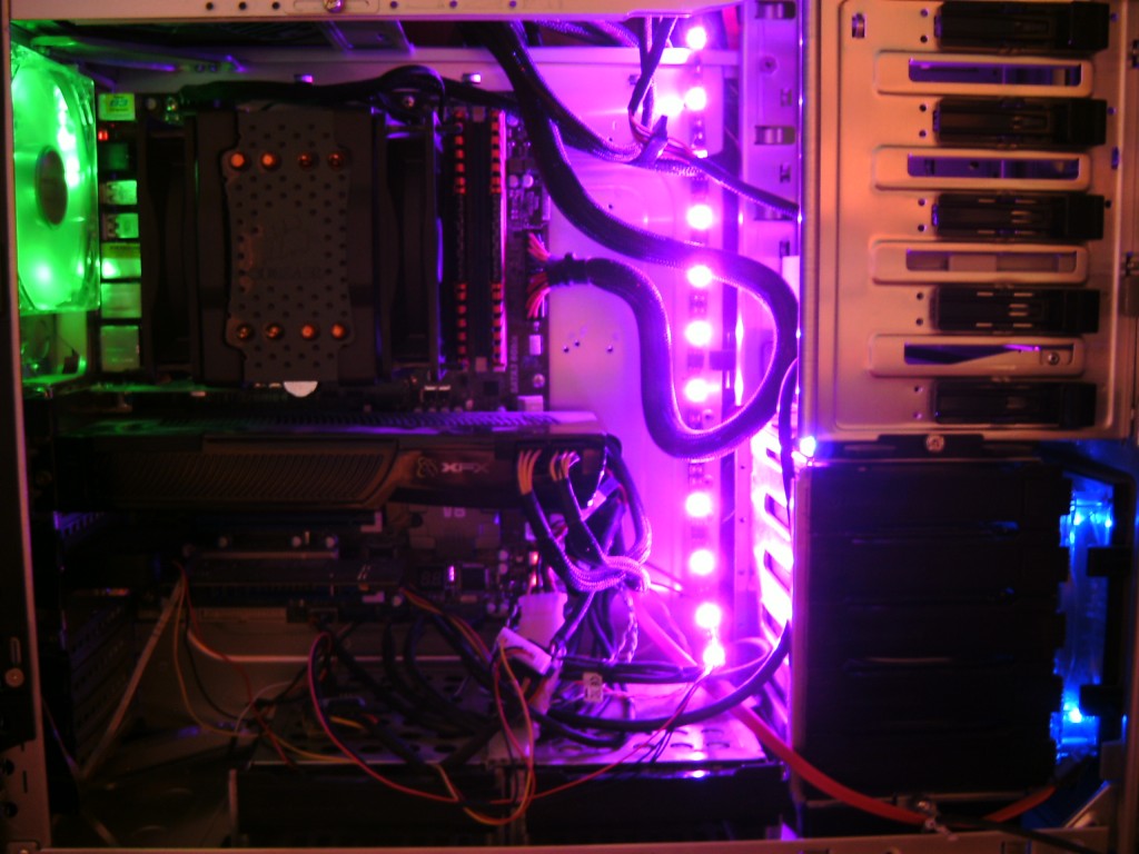
This project uses an ATtiny45 microcontroller to control an RGB LED strip based on CPU usage. It’s a cool-looking project that uses the V-USB library to communicate with the PC without needing a USB-to-TTL serial converter.

AVR USB RGB LED Controller 

Hardware

The project uses an ATtiny45 microcontroller and ZVN4306A MOSFETs to control the RGB LED strip, with each color consuming only about 90mA of current. The MOSFETs are more efficient and produce less heat, allowing for more current to flow.

Firmware

The firmware uses Timer 0 and Timer 1 to implement PWM control of the LED strip at 500Hz, and Timer 0 also keeps track of milliseconds for idle timeout. The EEPROM saves the delay setting every 4 seconds, which helps extend the lifespan of the EEPROM and the LED color transition time. When the idle timeout is reached, the LED strip starts cycling through blue, green, and red colors until it receives USB data again.

Host Program

The host program is written in C and is compatible with Windows and Linux. It can set the LED color based on CPU usage or set a single static color. The setting is saved to the EEPROM, so it will restore to the previous setting when the PC is restarted.

Alternative