Misc

Successful Repair of Samsung HT-C460 Home Theater System: Capacitor Failure Diagnosis and Repair

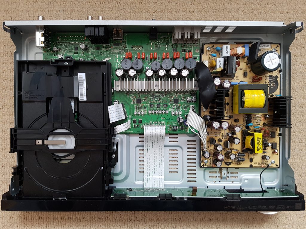
My old Samsung HT-C460 home theater system has suddenly started going into protection mode – it displays “PROT” on the screen and then shuts down after a few seconds. I haven’t used its DVD player function for years, only using it to transmit TV audio, but I want to try to diagnose and repair it to extend its lifespan.

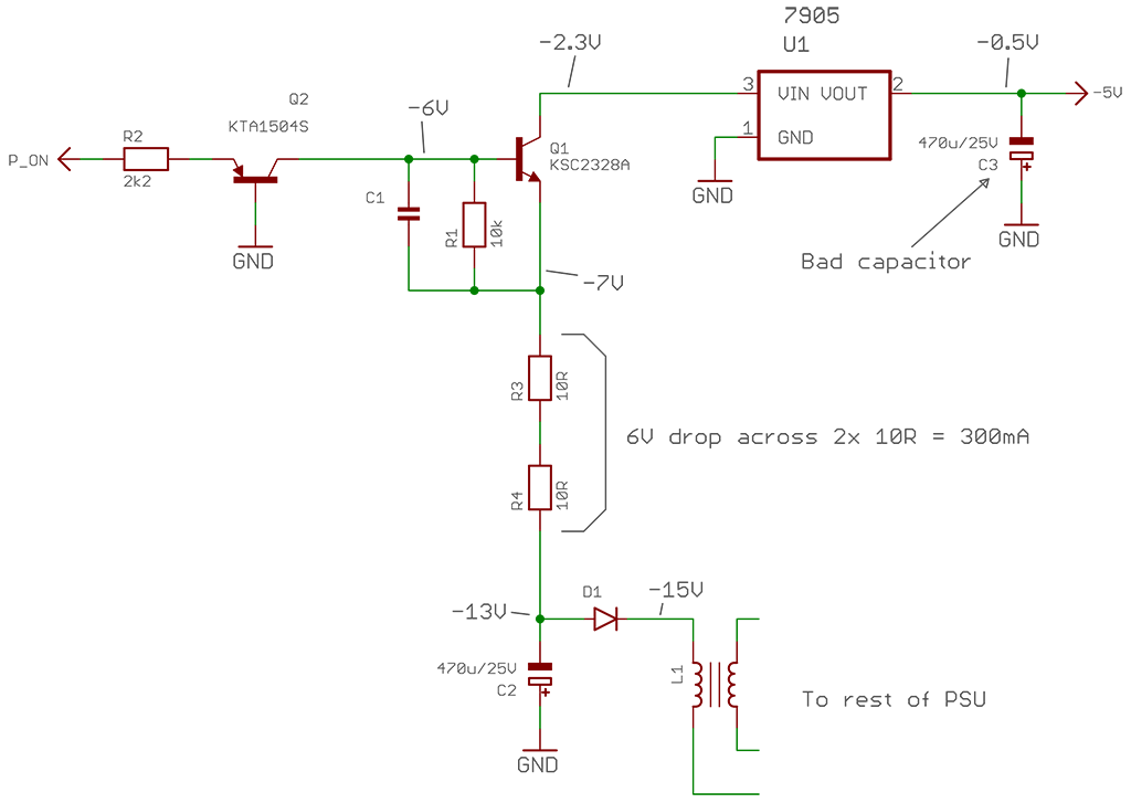
I carefully opened up the device and methodically checked for any burnt components, such as commonly seen bloated capacitors, but didn’t find anything out of the ordinary at first glance. I then checked the power supply area, verifying that the output voltages were correct, which are usually printed on the PCB. As a result, I discovered that the -5V rail was only outputting around -0.5V, which seemed very suspicious.
A bit of reversing engineering and probing around the power supply’s -5V rail resulted with this schematic and voltage readings:

I later searched for the part number of the PSU board “AH41-01311A” and found the full schematic anyway,
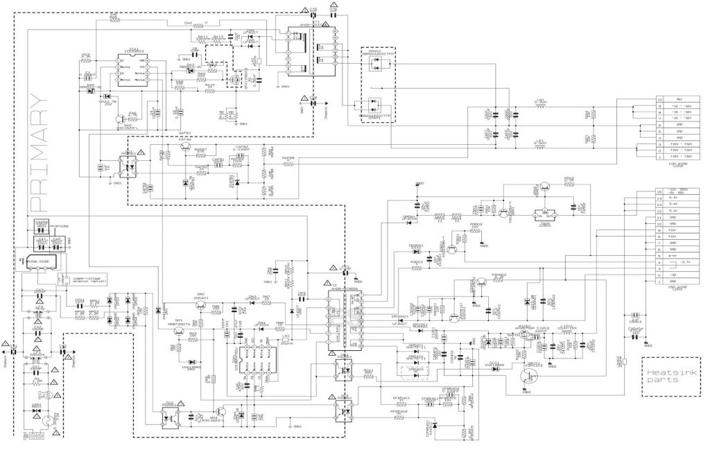
A 6V drop across two 10R resistors indicates a current consumption of 300mA. This also means that each resistor is dissipating 900mW of power, which is too much for its small 0805 package. It’s…

Free Chip Sample Acquisition Sharing

Everyone loves free stuff! I’m thrilled to share my experience of recently getting some free chip samples.

Atmel
3 day delivery from US to UK via DHL WW Express

Maxim
5 day delivery from UK via Royal Mail.

Microchip
2 week delivery from Thailand

I also ordered STD75N3LLH6 x4 and STD155N3LH6 x4 (MOSFETs) from ST, but they declined my request, I think I ordered too many, 3 of each part is usually the maximum.
So in total, these samples are worth around £45! (ex. VAT) The DS3231 RTC ICs being the bulk of it, at £5-£7 each.
Stay tuned for upcoming projects using these parts!

Update – 23 May 2013
Atmel
3 day delivery from US to UK via DHL WW Express

Ti
2 day delivery from US

ST
1 week delivery from US

About LCD Image Viewer

This is a rapid project I’ve worked on, using a 1.8-inch color LCD display from Ebay. The microcontroller code is very simple, initializing the display and then waiting for serial data to be sent directly to the screen. The host program handles image processing, opening the image and resizing it, displaying it in a preview window, and converting it to 12, 16, or 18-bit color during upload.

Additionally, I’ve added various interactive features to the preview window, including image rotation, scaling, and movement, making the project more practical and interesting.

Setup is wired as follows –

LCD pinArduino Uno pin
VCC5V
BKLGND
RESET**RESET
RS9
MISO*12
MOSI11
SCLK13
LCD CS10
SD_CS*4
GNDGND

* These are only needed if you’re using the SD slot on the back of the LCD
** Connect RESET to make the LCD reset along with the controller, if you don’t need that then leave disconnected or connected to 5V

Downloads

LATESTLCDImageViewer_20121026.zip (2.07 MB)
Host program and source (C# .NET), Arduino sketch code, Arduino LCD library and normal AVR C code (you can probably get it working on an ATtiny25)
MD5: DD6AC95ABD72318BFEA2B04F30F058BC

This article discusses three development…

IR Interferer Circuit Based on 555 Timer: Notes on Power Supply Voltage and Transistor Selection

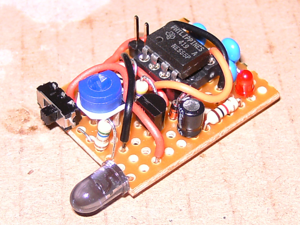
I built a simple circuit based on a 555 timer to interfere with infrared (IR) communications such as TV remote controls. When I first made it (October 2011), the circuit was unreliable in interfering with IR signals and eventually stopped working. It wasn’t until I recently bought a mini DSO that I discovered the circuit required at least 6.5V to reach the 38KHz frequency, while the 9V battery I was using was running out of power and couldn’t provide enough energy to reach 38KHz. After connecting it to a clean 9V power source and adjusting it to 38KHz with the help of the mini DSO, the interferer finally worked perfectly.

It’s worth noting that the transistor, 470R and 5R6 resistors, and 1N4148 diode form a constant current source of approximately 125mA to drive the IR LED. This will make the transistor quite hot. With a 9V power supply voltage and an LED Vf of 1.6V, the voltage drop across the transistor will be 6.8Vce, producing 850mW of heat at 125mA. This is actually higher than the rated 630mW of the 2N4401 transistor I used, so please make sure to choose the correct transistor to avoid problems.

[Schematic source (50 – 555 Projects on Talking Electronics)]

LED Flashing Circuits Design

Apart from using LEDs as power indicators or Joule thieves, I haven’t really used them much, so maybe it’s time to create something really fancy! 😊

I searched for some LED flashing circuits that can control at least 4 LEDs with minimal components, and finally found two circuits that I liked, both using Schmitt trigger oscillators, one that makes LEDs fade in and out, and another that feeds BCD to a 7-segment driver IC, making 7 LEDs flash randomly. 

Fader [HERE]
Random flasher [HERE]

Push-Pull Circuit

The push-pull circuit uses one Schmitt trigger for each LED, and since Schmitt trigger ICs usually have 6 triggers, it’s no problem to make 6 LEDs fade in and out at different rates. The downside of this circuit is that it will never fully turn on the transistor/LED, with a maximum current of only 4mA through the LED.

Since I want the LEDs to fade in and out at different rates, I couldn’t use the same resistor/capacitor values for all oscillators. Here is the table of resistor values used for each oscillator, with all capacitors having the same value (2.2uF / 22uF).

LeadR1R2R3
1100k4.7k47k
215k+27k2.2k15k
327k+47k4.7k47k
447k+100k4.7k47k

PWM Fan Controller Design Based on 555 Timer

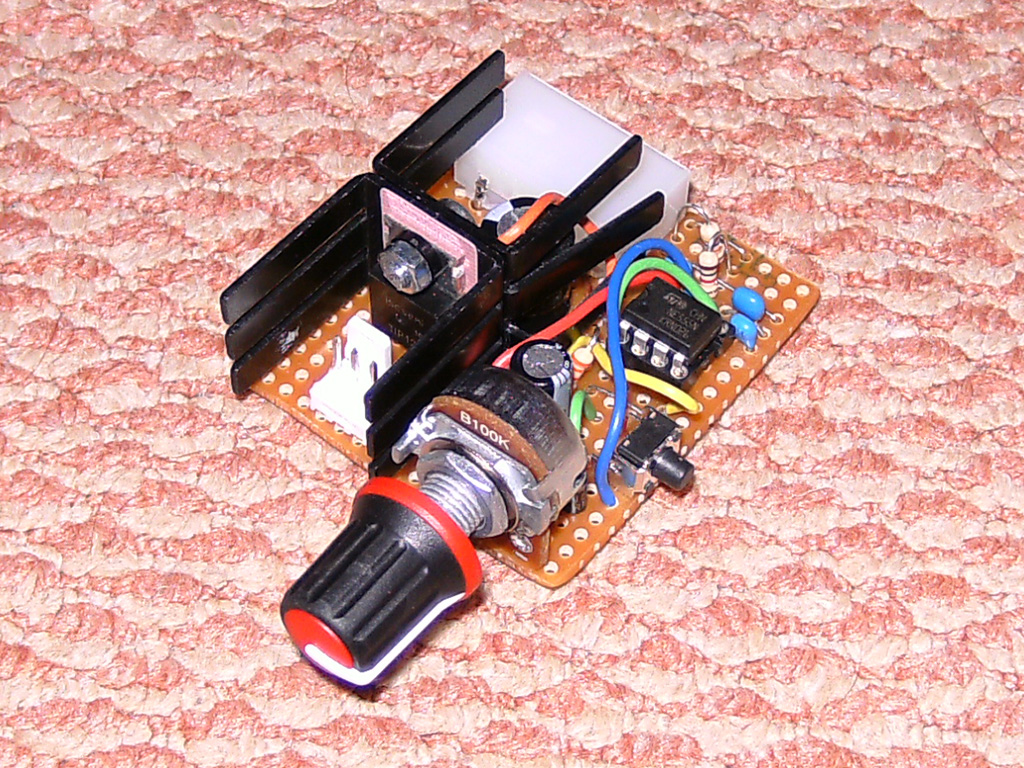
I designed three slightly different PWM fan controllers based on the 555 timer, used to control a large server fan – Delta FFB1212EHE, with a peak current of 3A and a normal load of 2A. The other features of these controllers include: boosting the fan to 100% for the first few seconds after power-on, and a “turbo” button to set the fan speed to 100% while pressed.

Version 1 (July 2010) of the controller did not work as expected during startup, staying at 0% instead of 100%. Another problem was that it would occasionally slow down to almost stopping, and I had to reset it to recover normal operation. I don’t know what caused this problem, but it seems to have no effect on later versions.

Version 2 (January 2011) fixed the startup boost problem by using a PNP output transistor. I changed the startup boost timer to reduce component count, but now the timer capacitor has a slow discharge time. Because of this, turning the controller off and back on too quickly would bypass the startup boost, as the capacitor voltage would still be above the 555 reset voltage threshold (~0.7V).

Version 3 (February 2011) is the same as Version 1, but with a PNP output transistor instead of …

Joule Thief Circuit: A DIY Experiment and Comparison

If you’ve never heard of a Joule Thief, it’s a simple voltage booster circuit that can power small loads like LEDs using a single battery, even ones that other devices consider “dead”.[Wikipedia article]

I built two versions of the Joule Thief circuit. One is the common version, using a single transistor, resistor, and coil, as shown in Wikipedia articles. The other version uses 2 transistors, 3 resistors, a capacitor, and an inductor, which I found online.[Here]

Both versions work well, but there are differences between them. The common version can operate at a lower voltage, around 0.6V, but consumes more current. The other version consumes much less current, 12mA, and 60mA at 1.3V, resulting in a slightly lower brightness, but with a small difference. In the common Joule Thief, I used a 2N4401 transistor, and in the other Joule Thief, I used a 2N3904 transistor.

During the experiment, I also tried to optimize their efficiency, observing their performance at different voltages. I found that both versions work well, but they have differences in voltage and current, and the right version should be chosen based on the actual situation.

Homemade FM Radio Transmitter Experience

I recently made a small FM radio transmitter, which can broadcast within a range of 100m-200m with a 12V power supply, and the audio quality is decent. The microphone of this transmitter is very sensitive, and with a 5pF-30pF variable capacitor, it can be tuned between 87.5MHz and ~98MHz. However, at higher frequencies, the transmitter becomes less stable and more difficult to tune.

During use, I found that the transistors and capacitors of the transmitter would change frequency due to heat, mainly caused by the Q2 transistor. Although the heat change is small, it still affects the stability of the transmitter.

I referred to the three circuit diagrams in the link, using a TL062 dual op-amp instead of a TL061 single op-amp, and added a switch to select between microphone and audio jack input. Moreover, I replaced R4 (100K) with a variable resistor to observe how its value change affects audio quality. The result shows that the value change of R4 has little or even negative effect on audio quality.Schematic source