Rev Up the Future: Building the Ultimate Autonomous RC Car with EaseCar

Get ready to revolutionize the world of remote-controlled cars with EaseCar, a cutting-edge project that’s about to take autonomous driving to new heights. Imagine a car that not only responds to your every command, but also navigates through obstacles with ease, all while live-streaming its journey to the world.

What sets EaseCar apart is its innovative fusion of multiple technologies, creating a seamless and immersive experience that tackles real-world challenges. This isn’t just about controlling a car with voice or gestures – it’s about creating a futuristic vehicle that can think for itself.

As a seasoned developer with a passion for IoT, I wanted to push the boundaries of what’s possible with intelligent hardware and software. I envisioned a project that would not only impress, but also provide tangible value to users. That’s why I embarked on this ambitious journey, combining the latest advancements in Intel Edison, computer vision, and machine learning to bring EaseCar to life.

In this series of tutorials, we’ll take you on a step-by-step journey to build EaseCar from the ground up. Whether you’re an experienced…

LED Flashing Circuits Design

Apart from using LEDs as power indicators or Joule thieves, I haven’t really used them much, so maybe it’s time to create something really fancy! 😊

I searched for some LED flashing circuits that can control at least 4 LEDs with minimal components, and finally found two circuits that I liked, both using Schmitt trigger oscillators, one that makes LEDs fade in and out, and another that feeds BCD to a 7-segment driver IC, making 7 LEDs flash randomly. 

Fader [HERE]
Random flasher [HERE]

Push-Pull Circuit

The push-pull circuit uses one Schmitt trigger for each LED, and since Schmitt trigger ICs usually have 6 triggers, it’s no problem to make 6 LEDs fade in and out at different rates. The downside of this circuit is that it will never fully turn on the transistor/LED, with a maximum current of only 4mA through the LED.

Since I want the LEDs to fade in and out at different rates, I couldn’t use the same resistor/capacitor values for all oscillators. Here is the table of resistor values used for each oscillator, with all capacitors having the same value (2.2uF / 22uF).

LeadR1R2R3
1100k4.7k47k
215k+27k2.2k15k
327k+47k4.7k47k
447k+100k4.7k47k

PWM Fan Controller Design Based on 555 Timer

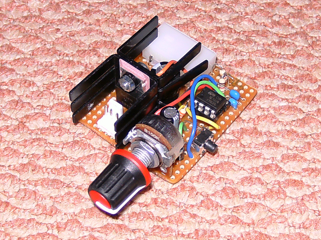
I designed three slightly different PWM fan controllers based on the 555 timer, used to control a large server fan – Delta FFB1212EHE, with a peak current of 3A and a normal load of 2A. The other features of these controllers include: boosting the fan to 100% for the first few seconds after power-on, and a “turbo” button to set the fan speed to 100% while pressed.

Version 1 (July 2010) of the controller did not work as expected during startup, staying at 0% instead of 100%. Another problem was that it would occasionally slow down to almost stopping, and I had to reset it to recover normal operation. I don’t know what caused this problem, but it seems to have no effect on later versions.

Version 2 (January 2011) fixed the startup boost problem by using a PNP output transistor. I changed the startup boost timer to reduce component count, but now the timer capacitor has a slow discharge time. Because of this, turning the controller off and back on too quickly would bypass the startup boost, as the capacitor voltage would still be above the 555 reset voltage threshold (~0.7V).

Version 3 (February 2011) is the same as Version 1, but with a PNP output transistor instead of …

Joule Thief Circuit: A DIY Experiment and Comparison

If you’ve never heard of a Joule Thief, it’s a simple voltage booster circuit that can power small loads like LEDs using a single battery, even ones that other devices consider “dead”.[Wikipedia article]

I built two versions of the Joule Thief circuit. One is the common version, using a single transistor, resistor, and coil, as shown in Wikipedia articles. The other version uses 2 transistors, 3 resistors, a capacitor, and an inductor, which I found online.[Here]

Both versions work well, but there are differences between them. The common version can operate at a lower voltage, around 0.6V, but consumes more current. The other version consumes much less current, 12mA, and 60mA at 1.3V, resulting in a slightly lower brightness, but with a small difference. In the common Joule Thief, I used a 2N4401 transistor, and in the other Joule Thief, I used a 2N3904 transistor.

During the experiment, I also tried to optimize their efficiency, observing their performance at different voltages. I found that both versions work well, but they have differences in voltage and current, and the right version should be chosen based on the actual situation.

Homemade FM Radio Transmitter Experience

I recently made a small FM radio transmitter, which can broadcast within a range of 100m-200m with a 12V power supply, and the audio quality is decent. The microphone of this transmitter is very sensitive, and with a 5pF-30pF variable capacitor, it can be tuned between 87.5MHz and ~98MHz. However, at higher frequencies, the transmitter becomes less stable and more difficult to tune.

During use, I found that the transistors and capacitors of the transmitter would change frequency due to heat, mainly caused by the Q2 transistor. Although the heat change is small, it still affects the stability of the transmitter.

I referred to the three circuit diagrams in the link, using a TL062 dual op-amp instead of a TL061 single op-amp, and added a switch to select between microphone and audio jack input. Moreover, I replaced R4 (100K) with a variable resistor to observe how its value change affects audio quality. The result shows that the value change of R4 has little or even negative effect on audio quality.Schematic source