Tutorials

DIY Electronics: Building Your Own Hardware from Scratch


Demystifying the Arduino Uno: A Comprehensive Guide to its PCB, Components, and Breadboarding Essentials

This tutorial aims to provide a thorough understanding of the inner workings of the Arduino Uno, breaking down its printed circuit board (PCB) and components, and explaining how to replicate its functionality using just a few essential parts. By the end, you’ll have a clear grasp of each component’s role and which ones are crucial to the board’s operation.

The Microcontroller

When making projects with an Arduino, we tend to think of them like the image below. We have a sensor connected, and maybe an LED, and we connect those components to the Arduino’s pins. Then, our code can be uploaded to use those components as inputs and outputs.
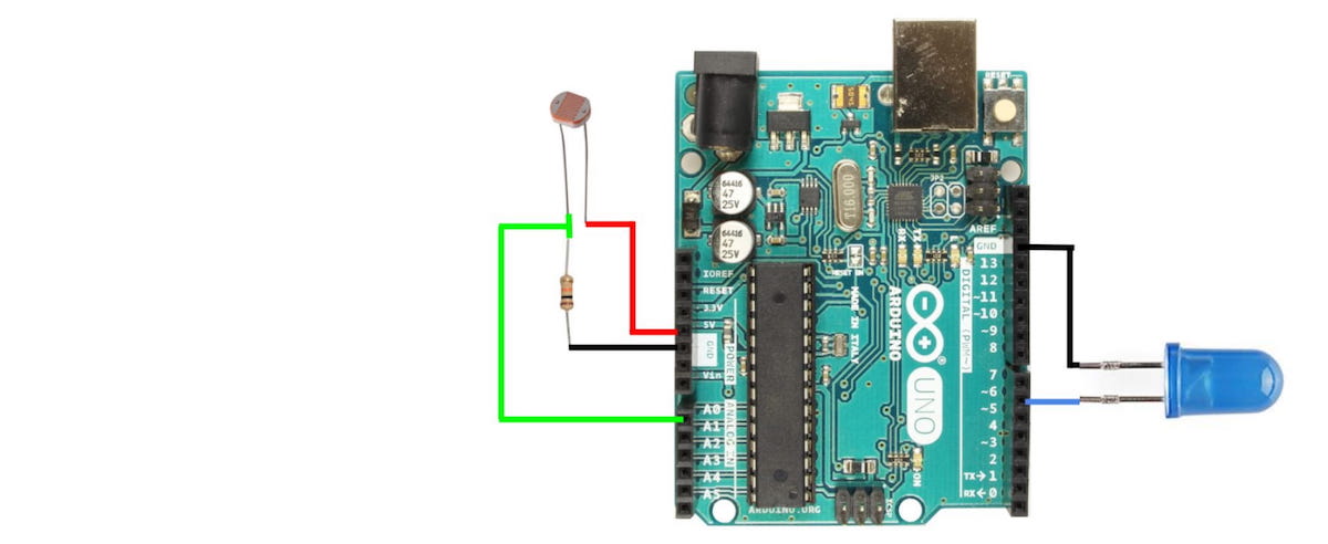
In Homemade Hardware, we make our own circuit boards, so it would be helpful to go through the Arduino Uno to understand all its inner workings and design decisions.

The Arduino Uno is probably the most popular microcontroller among makers and students, since its release in 2010. This is still the case today, because of it’s giant body of open source software, and ease of use.

This popularity is centralized around…

Unlocking the ATtiny85: A Beginner’s Guide to Programming and Hacking

Powerful yet Pocket-Sized: Getting Your Brand New ATtiny85 to Run Arduino Code from Scratch

This guide will walk you through the process of preparing your brand new ATtiny85 microcontroller to run your Arduino code, unlocking the convenience of a small yet powerful device.

ATtiny85 Pinout

The diagram below shows the details of the ATtiny85’s pinout. Notice the Arduino labels given to the 5 GPIO, plus all the other ways the pins are named.

Below is a much simpler image, showing just what is needed for running your Arduino code.

Breadboard Setup

Start by placing the ATtiny85 in the middle of a breadboard. Connect the Vcc and GND pins to the Power and Ground rails on your breadboard.

Notice that on my breadboard, I have connected the Power and Ground rails on either side, to make it easier to organize things.

It is strongly recommended to put a 0.1uF capacitor on the Vcc pin of the ATtiny85, with the other side going to ground. This will help get rid of any noise on the power line.

Finally, place a 10k Ohm resistor between the Rest pin and Power (Vcc). This will prevent the ATtiny85 from accidentally resetting.

Turn Arduino Uno into ISP

This guide will use an Arduino Uno as our ISP (In-System-Programmer).…

aspberry Pi 4 PCIe Bridge Chip Solution

After seeing Thomasz Mloduchowski and Colin Riley‘s successful project of bridging the PCIe bus to a USB 3.0 port on the Raspberry Pi 4, I felt extremely motivated! After reading the comments on hack-a-day, I decided to give it a try myself!

So, I designed a PCIe bridge “chip” that can simply replace the VL805 USB 3.0 controller chip on the Pi, allowing access to the PCIe bus on the USB 3.0 port. However, this also means that all USB functionality on the Pi will be lost. If you encounter network issues and need to connect a keyboard, this might be a bit troublesome.

Fortunately, there’s a solution. The USB-C power connector appears to be able to function as a USB host, as long as 5V power is provided through the GPIO header, allowing a keyboard to be connected. This is a very practical solution that can meet our needs.

The bridge “chip” is a 0.8mm thick PCB from OSHPark with copper pads in the same locations as a real VL805 QFN68 IC package, then traces connecting the PCIe pads to the USB pads that connect to the upper USB 3.0 port. RESET, WAKE and a few other signals were also connected to the lower USB 3.0 port.

PCIe SignalDirectionUSB Signal
REFCLK+Host -> DeviceD-

EaseRobot – A Cutting-Edge Autonomous Robot

Welcome to EaseRobot, a cutting-edge autonomous robot designed to revolutionize home automation. This innovative DIY robotics project aims to create a sophisticated house-bot that can navigate and interact with its environment. In this series, we’ll delve into the project’s details, starting with the concept, hardware selection, and initial software development.

Inspired by the possibilities of modern robotics, EaseRobot is built around a Raspberry Pi 3, Model B, leveraging its processing power and versatility. By harnessing the capabilities of the Robot Operating System (ROS) and Raspberry Pi, we can focus on developing the robot’s features rather than building a custom processor board from scratch.

EaseRobot is designed to perform various tasks, including facial recognition, speech synthesis, and autonomous locomotion. Our robot will be equipped with a 7″ touchscreen display and a camera module, enabling it to interact with users and navigate its surroundings. With ROS, we can develop and test nodes for the system, simulate the robot’s behavior, and refine our code.

In this project, we’ll explore various “missions”…

Bluetooth Smart Monitoring System V2.0

This article only provides a sneak peek into the new features of the network monitor.I’d recommend having a look at the original post first.

  • New PCB design
    The new PCB is now an almost single board design, just a separate board for the USB connector. The old monitor had a small main board which connected to the LCD and Bluetooth modules. This new board has everything soldered straight on.
  • Revamped microcontroller code
    Refactored a lot of the microcontroller code, reduced RAM usage and improved performance a little bit.
  • New router program
    The router program is now completely written in C! Uses much less CPU time than the old shell script.
  • New host program
    Written in C# .NET and uses LibUsbDotNet. It’s still in early development, but at the moment allows uploading images (takes around 2.5 – 3 seconds to upload), drawing stuff (mouse click and drag) and controlling the display brightness.
  • Other new features
    New efficient binary protocol instead of a text protocol.
    Added a temperature sensor since there was a lot of room left on the PCB, however this turned out to be a bit useless for measuring the room temperature because of the heat dissipated by nearby parts, mainly

From Scratch to Smart: Creating a Custom Lock with EaseLock

Create a custom smart lock device for your existing door that integrates an Atmega328 microcontroller, HC-05 Bluetooth module, and relay module, enabling remote operation from any paired Android device.

In this project, We will show you how to build a comprehensive prototype of smart lock step by step with minimal cost.

The initial intent with this tutorial was to show you that you can make build this project even if you have little experience with all of the various parts (AVR chips, Bluetooth, Android). We still believe you can if you follow the steps in this tutorial.

Getting Started

Hardware Tutorial

Create a custom smart lock device for your existing door that integrates an Atmega328 microcontroller, HC-05 Bluetooth module, and relay module, enabling remote operation from any paired Android device.

In this project, I will show you how to build a comprehensive prototype of smart lock step by step with minimal cost.

Introduction

Developing a product that goes beyond software requires mastering multiple technologies, which can be a daunting task. However, this diversity can also be the most fascinating aspect of the project.

Below is a rough diagram that provides a comprehensive…

High-Precision Timing Library for AVR

This lightweight library is specifically designed for millisecond-level time tracking. It supports the “unsigned long long” data type, allowing it to accurately track up to 584.9 million years! Additionally, it can adapt to clock frequencies of up to 20MHz, with most common frequencies having no timing errors.

Compared to Arduino’s built-in millis() timer, this library is especially useful when running at clock frequencies of 8MHz or below or when tracking time for more than 50 days.

Download from GitHub

Brief comparison against the Arduino millis()

Arduino millis()

  • Microsecond support
  • Doesn’t loose or gain time at any clock frequency
  • Loss of resolution at lower frequencies

This library

  • Faster execution
  • Less RAM used
  • Always updates millisecond count every millisecond
  • Support for ‘unsigned long long’ data type, 64 bit integer allows tracking time for up to 584.9 million years, Arduino millis() uses ‘unsigned long’ which goes up to 49.71 days
  • Uses CTC mode for the timer, which might make it a little bit more difficult to use the timer for multiple things

Accuracy at commonly used clock frequencies

ClockThis library (TIMER0)This library (TIMER1)

EaseWatcher: Smart Surveillance Made Easy

EaseWatcher is a comprehensive DIY smart surveillance system that empowers users to create a robust and customizable security solution for their homes or businesses. This innovative system combines cutting-edge technology with ease of use, allowing individuals to monitor and protect their properties with confidence.

With EaseWatcher, users can effortlessly connect multiple cameras, triggers, and alarm channels to create a seamless surveillance experience. The system’s modular design enables users to add or remove components as needed, making it an ideal solution for a wide range of applications.

EaseWatcher’s advanced features include:

  • Real-time video streaming and recording
  • Motion detection and alert notifications
  • Customizable alarm channels for instant notifications
  • Support for multiple camera types and protocols
  • Cloud-based storage for secure and convenient access

By leveraging the power of EaseWatcher, users can enjoy peace of mind knowing that their properties are protected and monitored around the clock. Whether you’re a homeowner looking to safeguard your family and assets or a business owner seeking to enhance security…

Microcontroller PWM Controller: A Design Based on ATtiny25 and MOSFET

I recently designed a PWM controller based on a microcontroller and MOSFET, which can control high-current loads. It’s a bit like a PWM controller based on a 555 timer, but now using a microcontroller and MOSFET instead of a 555 IC and transistor.

I made two versions, one with acceleration and deceleration switches, and another with a potentiometer. The controller uses an ATtiny25 microcontroller, running at 31.25KHz (8MHz internal RC/256 prescaler), powered by 3.3V. I used an STP36NF06L MOSFET, with a maximum 0.045Rds and 2.5Vgs, which is suitable for 3.3V power supply. The MOSFET produces only ~180mW of heat at 2A, which doesn’t require a heat sink.

In the circuit diagram, if using a 5V power supply, R1 should be changed from 100R to 150R to keep the current below 40mA. Zener diodes D1 and D2 are used for ESD protection, requiring a voltage rating above the uC power supply voltage and below the maximum gate voltage of the MOSFET. The STP36NF06L MOSFET can easily switch ~8A, but requires some heat sinks. The potentiometer selection also needs to consider the microcontroller ADC reading and current consumption.

Update – July 10, 2013

I recently designed a new …

EaseHome: Unlock the Future of Smart Home Automation

EaseHome is a revolutionary smart home chatbot that lets you control and monitor your home with ease. Using natural language processing and machine learning, EaseHome understands your voice commands and responds accordingly, making it easy to manage your home’s temperature, lighting, security, and more. With EaseHome, you can experience the future of smart home automation today.

Getting Started

EaseHome Tutorial

EaseHome: Unlock the Future of Smart Home Automation

Welcome to EaseHome: A Smart Home Chatbot Tutorial

Imagine being able to converse with your home, effortlessly asking questions like “What’s the current temperature?” or “Are all doors locked?” and even controlling your home’s settings with simple voice commands like “Set the kitchen temperature to 19°C!” This futuristic vision, inspired by movies like “Minority Report,” is now within reach. In this tutorial, we’ll explore how to integrate a cutting-edge text recognition system into a smart home system using the Microsoft Bot Framework and Language Understanding Intelligent Service (LUIS).

The Dream of a Smart Home