Projects

Smart AC Power Control: A Programmable Interface for Customized Automation


Based on the working principle of thyristor firing angle control, AC power can be controlled. The system uses a display unit to show the full power, and then the user can input the desired percentage to reduce the power to the load. To maintain the load power, the firing angle will be automatically adjusted. The project uses a lamp to make the input power equal to the required power. This process is achieved by connecting a TRIAC in series with the AC load. The system uses the 8051 microcontroller family. A keypad is used to input information to the microcontroller, with ZVS as a reference. An LCD display is used to display information.

AC Power Controller with Programmable Interference

The block diagram of AC power controller with programmable interference can be built with Microcontroller (AT89S52/AT89C51), Power Supply Block, Keypad, LM358 (Comparator), LCD Display, MOC3021, 1N4007, BC547, LED, Resistors, Capacitors, SCR. Keil µVision IDE and MC Programming Language: Embedded C

AC Power Controller with Programmable Interference Block Diagram

Power Supply

The power supply circuit can be built with a step-down transformer, which steps down …

Unlocking the 555 Timer: Creative Circuits and Projects for Engineers

The 555 timer is a versatile and widely used device in embedded system design, commonly employed in various electrical and electronics projects to generate precise clock pulses. Despite its popularity, many people remain unaware of its internal circuitry. In this article, we’ll delve into the inner workings of the 555 timer circuit, empowering you to build innovative projects and experiment with its capabilities.

Let me know if you’d like me to make any further changes!

555 Timer Circuits

The 555 timer integrated circuits are used to generate an  accurate square wave commonly used in many electronics circuits. The 555 timer circuit has designed with 20 transistors, 16 resistors, 2 diodes and a flip-flap. It can be operated in the range of 4.5v to 15v DC supply. The 555 timer IC has basically three functional parts such as;

Comparator

It is used to compare two input voltage levels which is inverting (-) one and non-inverting (+) terminals. If the voltage is high at the non-inverting terminal, then the output is high. The input resistance of ideal comparator is infinite.Voltage divider

As the input resistance is infinite in the comparator, so the…

Smart Email Notifier – WiFi Edition

I finally got rid of the A9G GPRS module and Vodafone network limitations! After moving into my new apartment, I found that the mailbox is right at the front door, which is within my WiFi network range. This gave me the opportunity to redesign the mail notifier, breaking free from the reliance on mobile networks. I cancelled the ATtiny402, battery charging, and GPS devices, and replaced them with the ESP-M2 WiFi module, allowing the mail notifier to connect to my WiFi network. The new design makes the mail notifier more streamlined and reliable, and I no longer have to worry about its stability issues.

General Operation

The ESP’s main task is to send an HTTP network request when mail arrives, and to maximize battery life, the ESP is only powered on when the switch is triggered, and then powered off after the request is completed, which usually takes around 4-10 seconds.

To achieve this, I designed a special circuit. The switch input is connected to a 74LVC1G98 logic gate, configured as a NAND gate with an inverted input. Normally, the switch input is pulled high through R1, and the gate output remains low, disabling the 3.3V voltage regulator.

When the switch is triggered, capacitor…

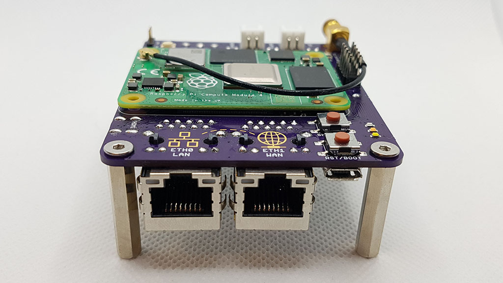
RouterPi – CM4 High-Performance Router Board

Another Raspberry Pi Router! I’ve always wanted to use a Raspberry Pi as my home internet router, but previous versions didn’t quite meet my requirements. I needed two Ethernet interfaces that could handle 1Gb traffic with low latency. The Pi 2 had 100Mb Ethernet, and the Pi 3 had 1Gb Ethernet, but it was shared on the USB 2.0 bus, limiting it to a few hundred Mbps. There were other Pi-like products, but their software and long-term support didn’t look promising. So, for the past decade, I’ve been using a small fanless Intel N3050 mini-ITX system with a Gigabyte N3050N-D3H motherboard, which had dual onboard Ethernet and could run Debian Linux on a USB stick.

Then came the Pi 4, which had its own bus and 1Gb Ethernet on USB 3.0! However, I was still unhappy about the CPU overhead and power consumption increase from having to connect the second Ethernet interface to a USB 3.0 hub. This was the main reason I created a PCIe bridge “chip” to add a PCIe network card. But a few months later, the Compute Module 4 was released, and now there’s the RouterPi board: an optimized re-write.

Hardware

  • Raspberry Pi Compute Module 4 with 2GB RAM & 8GB eMMC
  • 2x

Smart Home Security: The Perfect Integration of IoT and Access Control Systems

I recently moved into a two-story apartment, with an intercom system at the entrance of the building, located in the lobby area. Since I usually live upstairs, I want to find a way to remotely open the door without having to rush downstairs to the intercom every time someone presses the doorbell. It would be very convenient. Even better, if I could know when someone presses the doorbell when I’m not at home, that would be great! This way, I can handle doorbell events in a timely manner and won’t miss any important visits.

My apartment’s intercom system has a basic setup, including a buzzer, a button to unlock the hall door, and a speaker, but the microphone in my intercom doesn’t work. The system is powered by 14V AC, but it has an electrical noise problem. Moreover, the system lacks voltage spike suppression, and I often see a small arc when I press the button to control the unlocking of the hall door. This also causes the error counter on my broadband modem to increase by 1. To solve these problems, I need to pay attention to the following points:

  1. Solve the problem of the microphone not working.
  2. Reduce the impact of electrical noise.
  3. Add voltage spike suppression to

Intelligent Mobile Power Bank Sustaining Technology

Yes, I have encountered this situation where the USB mobile power supply keeps shutting down due to low current consumption when powering a project. This is a frustrating problem, as these mobile power supplies usually have overcurrent protection mechanisms that automatically shut down when detecting low current consumption.

To solve this problem, I designed a pulse-adjustable constant current source module based on a microcontroller, operational amplifier, MOSFET, and other components. This module can be connected to USB 3 directly, providing a stable current output and avoiding the mobile power supply shutdown issue.

The working principle of this module is to use the microcontroller to monitor current consumption and adjust the output current accordingly. The operational amplifier amplifies the current signal, while the MOSFET acts as a current switch to control the output current. By doing so, we can create an adjustable constant current source that meets the project’s current requirements while avoiding the mobile power supply shutdown issue.

The design of this module is very convenient, using a convenient USB interface that is easy to integrate with…

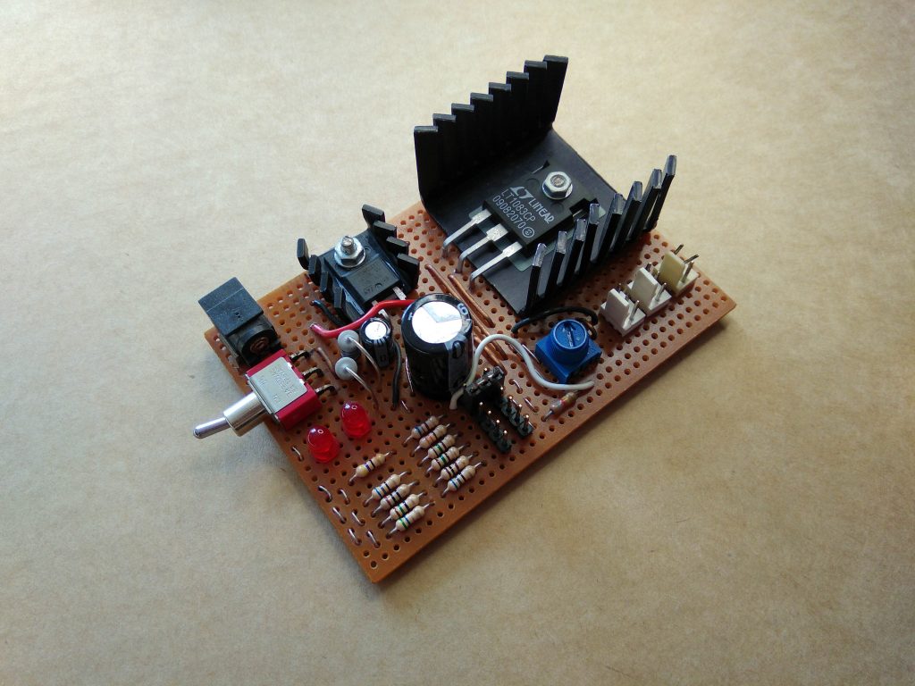
Custom Laptop Power Supply Project

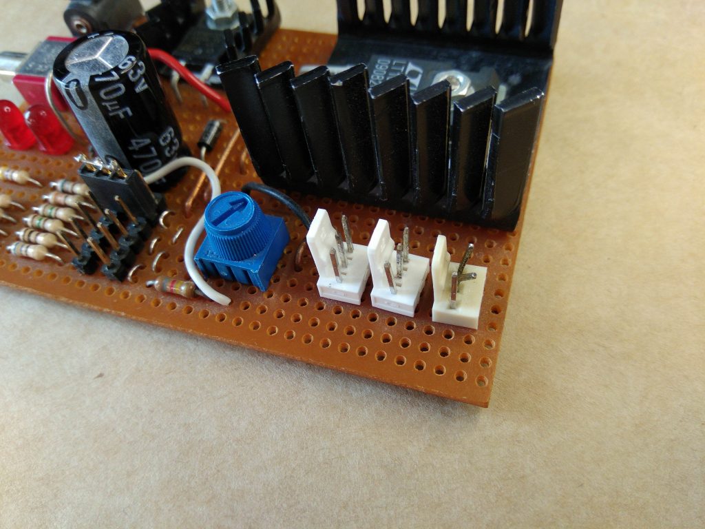
Your desktop power supply has been running for many years, still maintaining good performance, which is indeed a remarkable feat! However, the output power connector selection has some shortcomings, with the 3-pin header type connector not being suitable for this power output, which can easily lead to cooling issues.

It’s time to upgrade your power supply now! Consider using a better output power connector, such as MOLEX or SATA interfaces, which are more reliable and universal. Additionally, improving the heat dissipation design, such as adding heat sinks or improving the heat dissipation ventilation system, will also help to ensure stable operation of the power supply.

Furthermore, using more modern power management technologies, such as DC-DC converters or switching power modules, can improve the efficiency and reliability of the power supply. In summary, it’s time to upgrade your power supply to make it more stable, reliable, and efficient!

The old power supply
Messed up output connectors

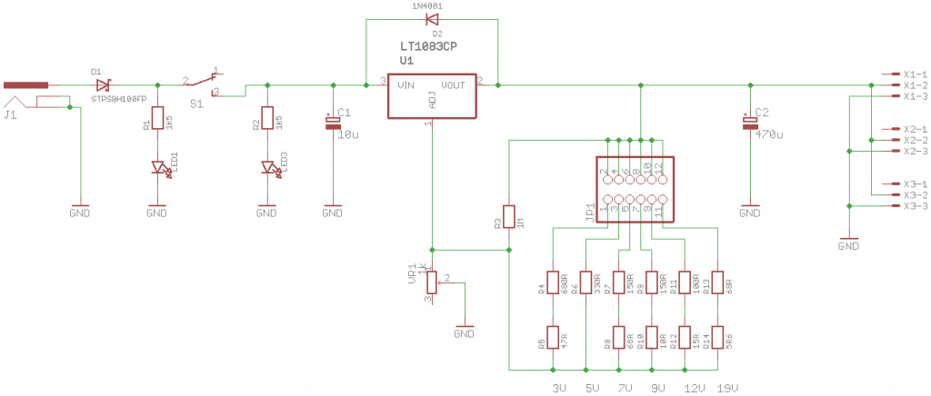
Old regulator schematic

A true desktop power supply typically comes with features such as adjustable current limiting and a display for voltage and current. However,…

aspberry Pi 4 PCIe Bridge Chip Solution

After seeing Thomasz Mloduchowski and Colin Riley‘s successful project of bridging the PCIe bus to a USB 3.0 port on the Raspberry Pi 4, I felt extremely motivated! After reading the comments on hack-a-day, I decided to give it a try myself!

So, I designed a PCIe bridge “chip” that can simply replace the VL805 USB 3.0 controller chip on the Pi, allowing access to the PCIe bus on the USB 3.0 port. However, this also means that all USB functionality on the Pi will be lost. If you encounter network issues and need to connect a keyboard, this might be a bit troublesome.

Fortunately, there’s a solution. The USB-C power connector appears to be able to function as a USB host, as long as 5V power is provided through the GPIO header, allowing a keyboard to be connected. This is a very practical solution that can meet our needs.

The bridge “chip” is a 0.8mm thick PCB from OSHPark with copper pads in the same locations as a real VL805 QFN68 IC package, then traces connecting the PCIe pads to the USB pads that connect to the upper USB 3.0 port. RESET, WAKE and a few other signals were also connected to the lower USB 3.0 port.

PCIe SignalDirectionUSB Signal
REFCLK+Host -> DeviceD-

Remote Mail Monitoring: Keep an Eye on Your Mailbox

I want to create a system that can notify me when the mailman delivers a package to my mailbox. Considering that my mailbox is located in the central hallway area, the mailman’s visit time is unpredictable, and I don’t have a window facing the road, so I can’t see the mailman’s arrival.

Here are some suggestions:

Install a smart mailbox: I can install a smart mailbox equipped with sensors and Wi-Fi connectivity, which will send a notification to my phone or email when the mailman delivers a package.
Use a motion detector: I can install a motion detector near the mailbox, which will detect the mailman’s movement and send a notification to my phone.
Mailbox camera: I can install a small camera near the mailbox, which will take a photo when the mailman delivers a package and send it to my phone.
Mailman signing system: I can work with my neighbors or building administrators to establish a mailman signing system, which requires the mailman to sign for confirmation when delivering a package, and then I will receive a corresponding notification.

These methods can help me receive notifications when the mailman delivers a package, solving my problem.

The mailboxes…

Rolling in Miniature: A Compact Electronic Die

Introducing a tiny, minimalist electronic die project that packs a punch! With just 7 LEDs, an ATtiny25V, a CR1616 coin cell battery, and some passive components, this device is incredibly compact, measuring only 18mm x 18mm in size, 4.9mm in thickness, and weighing a mere 2.1 grams.

https://youtube.com/watch?v=E05Uq4TWpRk

This tiny electronic die features a single button, the roll button, which triggers the die to cycle through numbers 1 to 6 when held down. When the button is released, the scrolling slows down until the final change, at which point it switches to a randomly generated number using the XORShift random number generator algorithm. The XORShift algorithm is lightning-fast, compact in code, and maintains excellent randomness, making it a perfect fit for this project. The final value flashes several times before the die powers off after a few seconds.

Battery Life

The dice is powered by a CR1616 coin cell with a capacity of around 50-60mAh.

Current draw:

StateCurrent @ 3V
Off<0.1uA
Active2.4mA (average)

Some battery life calculations:

Number of rolls24,000 @ 3 seconds per roll (a quick press of the roll button)
Total duration20 hours

Rolling the dice 20 times…