Insights

DIY Electronics: Building Your Own Hardware from Scratch


Demystifying the Arduino Uno: A Comprehensive Guide to its PCB, Components, and Breadboarding Essentials

This tutorial aims to provide a thorough understanding of the inner workings of the Arduino Uno, breaking down its printed circuit board (PCB) and components, and explaining how to replicate its functionality using just a few essential parts. By the end, you’ll have a clear grasp of each component’s role and which ones are crucial to the board’s operation.

The Microcontroller

When making projects with an Arduino, we tend to think of them like the image below. We have a sensor connected, and maybe an LED, and we connect those components to the Arduino’s pins. Then, our code can be uploaded to use those components as inputs and outputs.
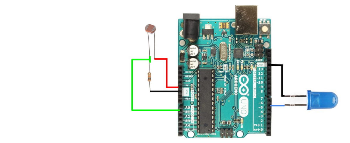
In Homemade Hardware, we make our own circuit boards, so it would be helpful to go through the Arduino Uno to understand all its inner workings and design decisions.

The Arduino Uno is probably the most popular microcontroller among makers and students, since its release in 2010. This is still the case today, because of it’s giant body of open source software, and ease of use.

This popularity is centralized around…

Unlocking the ATtiny85: A Beginner’s Guide to Programming and Hacking

Powerful yet Pocket-Sized: Getting Your Brand New ATtiny85 to Run Arduino Code from Scratch

This guide will walk you through the process of preparing your brand new ATtiny85 microcontroller to run your Arduino code, unlocking the convenience of a small yet powerful device.

ATtiny85 Pinout

The diagram below shows the details of the ATtiny85’s pinout. Notice the Arduino labels given to the 5 GPIO, plus all the other ways the pins are named.

Below is a much simpler image, showing just what is needed for running your Arduino code.

Breadboard Setup

Start by placing the ATtiny85 in the middle of a breadboard. Connect the Vcc and GND pins to the Power and Ground rails on your breadboard.

Notice that on my breadboard, I have connected the Power and Ground rails on either side, to make it easier to organize things.

It is strongly recommended to put a 0.1uF capacitor on the Vcc pin of the ATtiny85, with the other side going to ground. This will help get rid of any noise on the power line.

Finally, place a 10k Ohm resistor between the Rest pin and Power (Vcc). This will prevent the ATtiny85 from accidentally resetting.

Turn Arduino Uno into ISP

This guide will use an Arduino Uno as our ISP (In-System-Programmer).…

AVR-GCC 14.1.0 for Windows released: supports 32-bit and 64-bit systems

You plan to upload a version of AVR-GCC that is compatible with both 32-bit and 64-bit Windows, including Binutils, AVR-LibC, AVRDUDE, Make, and GDB. This means you will provide a complete development toolchain, making it convenient for Windows users to develop AVR microcontroller projects.

You also mention that, except for AVRDUDE, all binary files are built from source code using MinGW on a Debian virtual machine. This ensures the reliability and consistency of the binary files.

Providing both 32-bit and 64-bit Windows binary files is also convenient for users to choose the suitable version. Moreover, you will provide a bash script that allows users to easily build AVR-GCC, AVR-Binutils, AVR-LibC, and AVR-GDB from source code. This is particularly useful for users who need to customize or optimize the toolchain.

Overall, your upload will provide a convenient, reliable, and customizable AVR microcontroller development toolchain for Windows users.

Included tools

ToolVersion
GCC14.1.0
Binutils2.42
AVR-LibC2.2.0
GDB14.2
AVRDUDE7.2 (Not included in Linux release)
Make4.2.1 (Not included in Linux release)

Downloads

LATESTavr-gcc-14.1.0-x64-windows.zip (141

Hacking RAM SPD Data: A Step-by-Step Guide


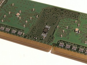
I recently purchased some low-power Mini-ITX motherboards, including the Gigabyte GA-N3050N-D3H and Biostar N3050NH. These motherboards use SO-DIMM DDR3 RAM, commonly found in laptops.

Although these two motherboards are very similar, the Gigabyte motherboard lacks some BIOS features and settings compared to the Biostar motherboard. One of the missing features is the inability to set the RAM frequency. I want to run the RAM at a minimum frequency of 800MHz, but the Gigabyte motherboard runs it at the normal frequency of 1600MHz. This means that the Biostar motherboard can reduce idle power consumption by about 0.12W, or around 2%, with just a simple switch.

To solve this problem, I need to modify the RAM’s Serial Presence Detect (SPD) data. The SPD data is a set of configuration parameters stored in a small EEPROM chip, which the BIOS reads during boot-up. Fortunately, the SPD EEPROM communicates using SMBus, which is largely compatible with I2C on Arduino.

The SPD EEPROM

Modifying the RAM’s SPD data is not a new concept, and there are already many tools and programs available online that can perform SPD operations. However, the software and hardware compatibility…

Intelligent Lithium Battery Charging Management System


In project development, we may encounter issues where the circuit fails to turn on and the battery fails to charge, even with an LED. To address this problem, this article will introduce a design for a battery charger with load sharing functionality to ensure correct battery charging and normal operation of the main circuit.
We will utilize Microchip’s popular charging IC, MCP73831/2, suitable for single-cell lithium polymer and lithium-ion batteries, with a maximum charging current of 500mA. Additionally, we will reference Microchip’s application note AN1149 for load sharing design to ensure the charger’s stability and reliability.

Charging Issues without Load Sharing

During the pre-charge and constant current charging stages, the charging IC’s current limit may cause insufficient battery charging. If the load’s current demand exceeds the charging IC’s limit, the battery will be forced to discharge instead of charging. For example, if the charging IC’s current limit is 40mA and the load requires 50mA, the battery will discharge by 10mA.

During the constant voltage charging stage, the charger typically waits until…

Bluetooth Module Communication: Configuration and Testing

A Simple Way to Make Your Project Wireless with Serial Bluetooth Modules

Using serial Bluetooth modules is a straightforward way to make your project wireless, as they can transparently transmit standard serial data to another connected Bluetooth module, without requiring additional code.

Adding Bluetooth to Your Project for Mobile Control

To add Bluetooth to your project for mobile control, simply insert a slave module and connect to it via your phone. However, getting two modules to communicate with each other requires understanding some basic concepts.

How Bluetooth Modules Work

Bluetooth modules work in slave and master modes. Slave modules cannot initiate connections with other Bluetooth devices, but can accept connections. Master devices can be set to master or slave mode, and in master mode, they can initiate connections with other devices. Be sure not to make the mistake of buying two slave devices! You need two master devices or one master and one slave device.

What to Note When Buying Bluetooth Modules

Sometimes, eBay sellers may not provide much information about their modules. To determine whether a module is a slave or master device, be sure to check the following:…

Microcontroller PWM Controller: A Design Based on ATtiny25 and MOSFET

I recently designed a PWM controller based on a microcontroller and MOSFET, which can control high-current loads. It’s a bit like a PWM controller based on a 555 timer, but now using a microcontroller and MOSFET instead of a 555 IC and transistor.

I made two versions, one with acceleration and deceleration switches, and another with a potentiometer. The controller uses an ATtiny25 microcontroller, running at 31.25KHz (8MHz internal RC/256 prescaler), powered by 3.3V. I used an STP36NF06L MOSFET, with a maximum 0.045Rds and 2.5Vgs, which is suitable for 3.3V power supply. The MOSFET produces only ~180mW of heat at 2A, which doesn’t require a heat sink.

In the circuit diagram, if using a 5V power supply, R1 should be changed from 100R to 150R to keep the current below 40mA. Zener diodes D1 and D2 are used for ESD protection, requiring a voltage rating above the uC power supply voltage and below the maximum gate voltage of the MOSFET. The STP36NF06L MOSFET can easily switch ~8A, but requires some heat sinks. The potentiometer selection also needs to consider the microcontroller ADC reading and current consumption.

Update – July 10, 2013

I recently designed a new …

From Arduino to AVR Microcontrollers: My Electronic Journey

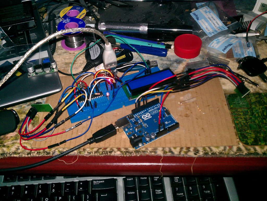
I’ve been following Arduino and finally got my hands on an Uno and a 16×2 character LCD with RGB backlight. This new electronic world is exciting me. For years, I’ve been interested in digital control devices like LCDs, wondering how to use them, but was always blocked by the complexity of microcontrollers. However, using Arduino’s LCD library made it easy to connect the LCD, and I quickly made a stereo audio VU meter and a basic FFT spectrum analyzer.

Next, I started exploring wireless technology. I bought NRF24L01 wireless modules, a USBASP AVR programmer, a USB to UART converter, and an ATMega168 microcontroller from Ebay. Using the Mirf library, I successfully made one controller change the LCD backlight color of another controller.

After getting used to the Arduino IDE, I wanted to dive deeper into how the code truly controls the chip. So, I downloaded Atmel Studio 6, the ATMega168 chip datasheet, and followed tutorials on avrfreaks.net to learn the basics of AVR microcontrollers, starting from timers and interrupts. Now, I’ve grasped the basics of AVR microcontrollers and have many project ideas involving AVR uCs.