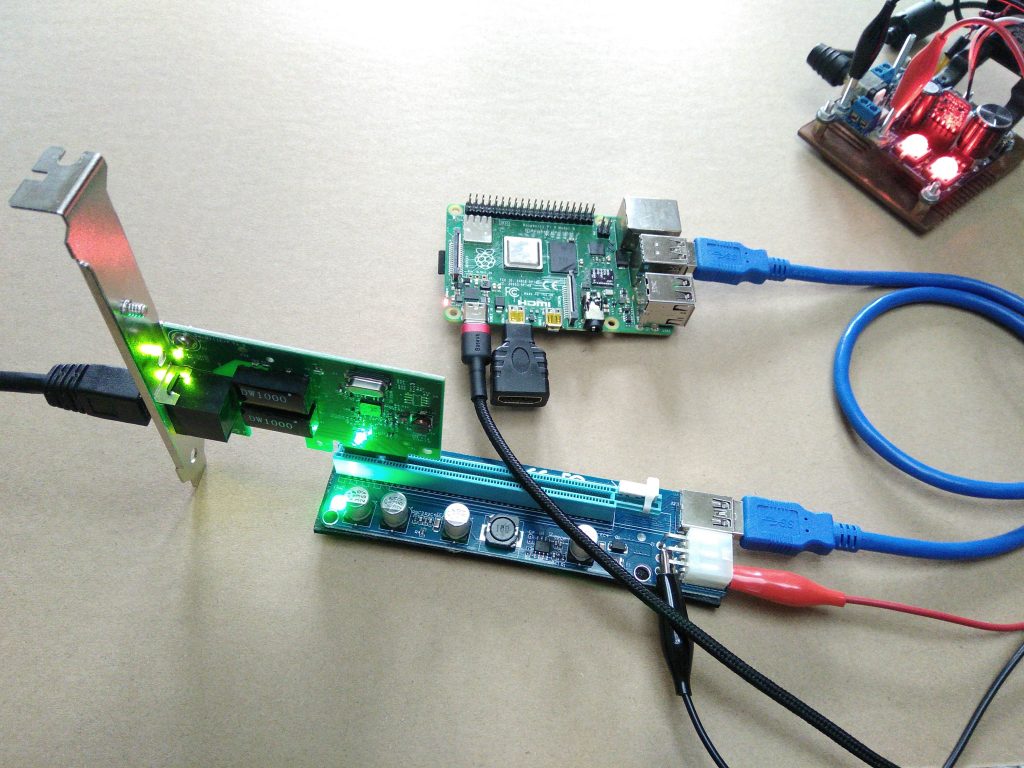
After seeing Thomasz Mloduchowski and Colin Riley‘s successful project of bridging the PCIe bus to a USB 3.0 port on the Raspberry Pi 4, I felt extremely motivated! After reading the comments on hack-a-day, I decided to give it a try myself!
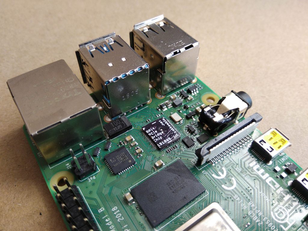
So, I designed a PCIe bridge “chip” that can simply replace the VL805 USB 3.0 controller chip on the Pi, allowing access to the PCIe bus on the USB 3.0 port. However, this also means that all USB functionality on the Pi will be lost. If you encounter network issues and need to connect a keyboard, this might be a bit troublesome.
Fortunately, there’s a solution. The USB-C power connector appears to be able to function as a USB host, as long as 5V power is provided through the GPIO header, allowing a keyboard to be connected. This is a very practical solution that can meet our needs.

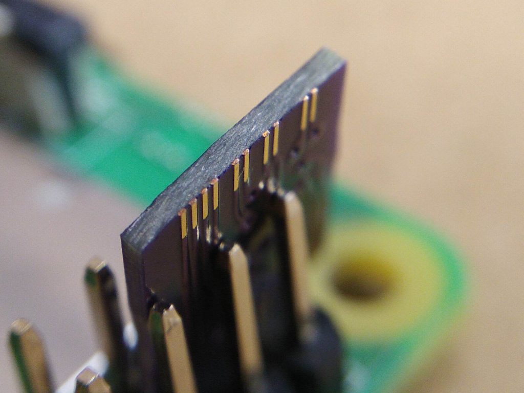
The bridge “chip” is a 0.8mm thick PCB from OSHPark with copper pads in the same locations as a real VL805 QFN68 IC package, then traces connecting the PCIe pads to the USB pads that connect to the upper USB 3.0 port. RESET, WAKE and a few other signals were also connected to the lower USB 3.0 port.
| PCIe Signal | Direction | USB Signal |
|---|---|---|
| REFCLK+ | Host -> Device | D- |
| REFCLK- | Host -> Device | D+ |
| HSO+ | Host (TX) -> Device (RX) | RX- |
| HSO- | Host (TX) -> Device (RX) | RX+ |
| HSI+ | Device (TX) -> Host (RX) | TX- |
| HSI- | Device (TX) -> Host (RX) | TX+ |
| RESET | Host -> Device | D- (lower port) |
| WAKE (not connected anywhere) | Device -> Host | D+ (lower port) |
| CLKREQ | Host -> Device | RX+ (lower port) |
| PONRST | Not a PCIe signal, connected like a reset pin on a microcontroller. | RX- (lower port) |
HSI and HSO (input and output) are really confusing! From the host controller’s perspective, HSO/TX connects to device RX, while HSI/RX connects to device TX. This makes me dizzy, TX, RX, device, host, via USB, which side is which…
Fortunately, there is a small hole near the center that allows any excess solder from the large grounding pad to be drained when placing the chip, preventing solder from being squeezed to the edge and causing a short circuit. The PCB design also needs to consider the limited distance between the copper and the edge, otherwise problems may occur. The manufactured PCB needs to be machined to the correct size so that the cross-section of the copper pad can be seen on the PCB edge, just like on a QFN package.
After replacing the VL805 with a bridge chip, I tried several spare PCIe cards. The first one was a Realtek RTL8168-based Ethernet adapter, but it didn’t work. I checked all the solder points, checked for conductivity and short circuits, and everything seemed fine. I tried various methods, such as removing capacitors and swapping the + and – signals for each signal, to prevent them from being swapped on the device side, as this is a feature of PCIe called polarity reversal, which the controller might not support.
However, the Pi still couldn’t detect them. It seemed unable to train the PCIe link, as shown in the dmesg log. I ordered a USB 3.0 expansion card with a VL805, identical to the one on the Pi. When it finally arrived, I plugged it in, and it was detected on the first try! I found a Realtek RTL8111-based Ethernet adapter, which also worked! After installing the RTL8111 driver, it was able to obtain an IP from the DHCP server, and I could ping the interface.link down.link up, 2.5 Gbps x1 (!SSC)

I wonder what aspects of the RTL8168 and ASM1083 are incompatible with the Raspberry Pi. Maybe they just don’t like the PCIe signals being transmitted through a lot of USB connectors and cables, causing them to malfunction. Or maybe it’s because the Raspberry Pi’s PCIe controller doesn’t support certain features or modes of these chips, resulting in them not being detected. Anyway, using the VL805 bridge chip and the RTL8111 chip finally helped me find a solution.
UPDATE 1: After using the ASM1184e PCIe switch, I found that the two expansion cards still couldn’t be detected. This means that it’s probably not a signal issue, but rather some other reason that’s preventing them from working. The device tree file has been modified to allow multiple PCIe devices, as described in Colins’ blog post. However, other cards can be used in the switch, it’s just these two that don’t work. I will continue to optimize and debug to find a solution.
UDPATE 2: No problem anymore! The issue with the ASM1083 was that I hadn’t connected the 5V power rail, and now the Pi can detect it. The RTL8168 still doesn’t work for some reason, but I’ll continue to optimize and debug to find a solution. Overall, progress is still going well!

Using the 4 USB 3.0 flash drives inserted into the VL805 expansion card for a quick test, the results show that the total read throughput is 3 Gbps through the 5 Gbps PCIe 2.0 link, while the theoretical maximum throughput is 4 Gbps. The read speed of the flash drives is almost at its maximum value, but may be slightly slowed down due to the overhead of switching between each drive during reading. Overall, the results are still very satisfying!
UPDATE: Another test using 5 USB flash drives, a USB hub, and a USB-to-Ethernet adapter also showed a maximum throughput of 3 Gbps, suggesting that this is a limitation of the VL805 or the CPU. Other benchmark tests using USB 3 SSDs on the RPi4 also reached a maximum value of 3 Gbps. This indicates that the limitation is likely hardware-related, rather than a software or driver issue.
Note that the RESET and WAKE lines on the adapter board should be cut, otherwise the RESET will be connected to GND, preventing the card from booting, and the WAKE will be connected to 5V, which may damage the device if the pin cannot withstand 5V. Then, the RESET line should have a 10k pull-up resistor connected to the 3.3V power supply, or connected to the D- signal of the USB 3.0 port on the bottom of the Pi.
Colin also mentioned that Thomasz’s setup encountered kernel panic issues, and I also experienced similar issues, but these problems seem to be caused by excessive PCIe card wobbling.
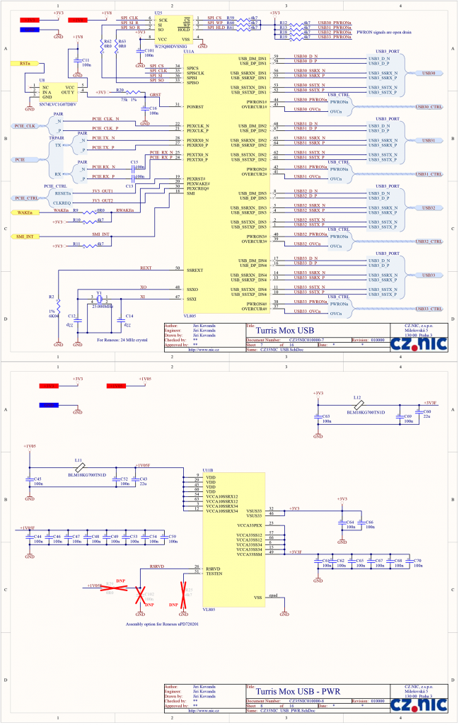
Fortunately, the PDF provides a complete schematic diagram for using the VL805 on pages 7 and 8, which is very convenient, as there is little information available about this chip.

PCB designs and things are on GitHub


