2018

Si4463 Wireless Library: A Wireless Communication Solution for AVR and Arduino

This is a library for the Silicon Labs Si4463 wireless IC, which has been used in (or will be used in) some of my projects. The Si4463 offers various configuration options, including modulation, data packet format, and CRC algorithm, and can output up to +20dBm (100mW) of power. Additionally, the Si4463 is also used in many pre-made modules, such as the HopeRF RFM26W and the Dorji_Com DRF4463F. The entire Si446x transceiver series should also be compatible with this library.

This library allows users to configure the chip to send and receive variable-length data packets (up to 128 bytes) and trigger callback functions when events occur (such as receiving new data packets and completing data packet transmission). These callback functions run directly from the interrupt routine, making the program’s response to events much faster than with polling libraries.

Download from GitHub
Documentation

Pinout

Si4463ATmega328Arduino UnoArduino MegaDescription
VCC3.3V3.3V3.3VPower (3.3V)
GPIO0
GPIO1
SDOB4 (18)1250SPI MISO
SDIB3 (17)1151SPI MOSI
SCLKB5 (19)1352SPI SCK
NSELB2 (16)1010

Hacking RAM SPD Data: A Step-by-Step Guide


I recently purchased some low-power Mini-ITX motherboards, including the Gigabyte GA-N3050N-D3H and Biostar N3050NH. These motherboards use SO-DIMM DDR3 RAM, commonly found in laptops.

Although these two motherboards are very similar, the Gigabyte motherboard lacks some BIOS features and settings compared to the Biostar motherboard. One of the missing features is the inability to set the RAM frequency. I want to run the RAM at a minimum frequency of 800MHz, but the Gigabyte motherboard runs it at the normal frequency of 1600MHz. This means that the Biostar motherboard can reduce idle power consumption by about 0.12W, or around 2%, with just a simple switch.

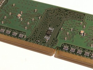
To solve this problem, I need to modify the RAM’s Serial Presence Detect (SPD) data. The SPD data is a set of configuration parameters stored in a small EEPROM chip, which the BIOS reads during boot-up. Fortunately, the SPD EEPROM communicates using SMBus, which is largely compatible with I2C on Arduino.

The SPD EEPROM

Modifying the RAM’s SPD data is not a new concept, and there are already many tools and programs available online that can perform SPD operations. However, the software and hardware compatibility…

MCP2221/MCP2221A USB Converter Open Source HID Library

This is an open-source library that aims to provide a multi-platform interface solution for interacting with Microchip’s MCP2221/MCP2221A USB-to-UART and I2C/SMBus serial converters. The library supports access to various functions of the converter, including 4 GPIO pins, 3 10-bit ADCs, and 1 5-bit DAC. Unlike Microchip’s proprietary DLL library, this project aims to provide an open-source, cross-platform alternative.

This library also makes use of HIDAPI.

Supported features:

FeatureStatus
ADCSupported
DACSupported
GPIOSupported
Interrupt inputSupported
Clock reference outputSupported
USB Descriptors
(Manufacturer, product, serial, VID, PID)
Supported
I2C/SMBLimited support, WIP
Flash password protectionNot yet implemented
C++ and C# wrappersNot yet implemented

Download from GitHub
Documentation

Bits of info about the MCP2221

  • Doesn’t use a crystal, only requires 1 small capacitor when powered with 3.3V or 2 capacitors when powered with 5V.
  • Available in a hacker friendly DIP package.
  • Has a remote wake function which when used in conjunction with the interrupt input can be used to wakeup the USB host (usually a PC), just

USB RGB LED Controller Based on AVR Microcontroller

Why not upgrade the CPU usage LED project to a general-purpose RGB LED controller? The current CPU usage LED controller uses a value between 0 and 255 to calculate the color it should be and then fades to that color. This is indeed quite limited; changing the color and fading method requires firmware updates. In contrast, a general-purpose RGB LED controller can let the host software handle all the work, and the controller only needs to be told what brightness the red, green, and blue LEDs should be, providing greater flexibility and scalability.

To simplify interactions with the controller, I developed a library that wraps all LibUSB content. With this library, you can achieve basic functionality with just a few lines of code (only 10 lines).


#include <rgbledctrl.h> int main() { rgbledctrl_init(); rgbledctrl_find(); s_rgbled_device* rgbLed = rgbledctrl_open(); rgbledctrl_setR(rgbLed, 200); // Set red value to 200 rgbledctrl_close(rgbLed); return 0; }

The library also has support for reading and writing to the EEPROM of the controller. Class wrappers for C++ and C# .NET are also provided.

Download from GitHub
Documentation

Bluetooth Smart Monitoring System V2.0

This article only provides a sneak peek into the new features of the network monitor.I’d recommend having a look at the original post first.

  • New PCB design
    The new PCB is now an almost single board design, just a separate board for the USB connector. The old monitor had a small main board which connected to the LCD and Bluetooth modules. This new board has everything soldered straight on.
  • Revamped microcontroller code
    Refactored a lot of the microcontroller code, reduced RAM usage and improved performance a little bit.
  • New router program
    The router program is now completely written in C! Uses much less CPU time than the old shell script.
  • New host program
    Written in C# .NET and uses LibUsbDotNet. It’s still in early development, but at the moment allows uploading images (takes around 2.5 – 3 seconds to upload), drawing stuff (mouse click and drag) and controlling the display brightness.
  • Other new features
    New efficient binary protocol instead of a text protocol.
    Added a temperature sensor since there was a lot of room left on the PCB, however this turned out to be a bit useless for measuring the room temperature because of the heat dissipated by nearby parts, mainly

Low-Power Microcontroller Applications in Smartwatches

Introduction

The main motivation behind this project was to see how much hardware and software I could cram into a small, watch-like device. I chose an OLED display because it’s only 1.5mm thick, doesn’t require a backlight, and each pixel emits its own light, making it look really cool. Initially, I planned to use a 0.96-inch display, but it turned out to be too small to fit all the components I wanted. Increasing the size to 1.3 inches proved to be the perfect solution.

https://youtube.com/watch?v=KrUJlZK1ct0

Hardware

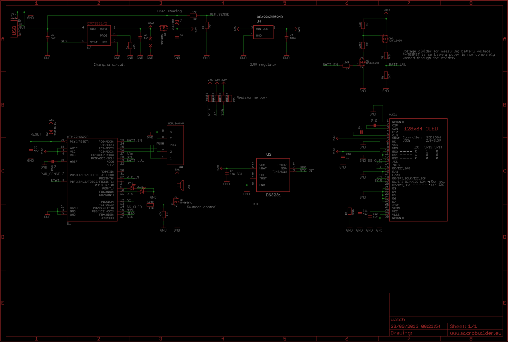
The hardware components of this watch include an Atmel ATmega328P microcontroller, a 2.5V voltage regulator, a Maxim DS3231M RTC, a 1.3-inch 128×64 monochrome OLED, 2 LEDs (red and green), a buzzer, a 3-route navigation switch, powered by a 150mAh LiPo battery, and charged via USB and 2 PCBs.

The microcontroller ATmega328P uses its internal 8MHz oscillator and runs at 2.5V. It consumes approximately 1.5mA in active mode and 100nA in sleep mode.

The DS3231M RTC is a high-precision clock chip with a small 8-pin package, including a built-in temperature-compensated MEMS resonator, with an accuracy of ±5ppm (±2 minutes 40 seconds per year). …

Intelligent Lithium Battery Charging Management System


In project development, we may encounter issues where the circuit fails to turn on and the battery fails to charge, even with an LED. To address this problem, this article will introduce a design for a battery charger with load sharing functionality to ensure correct battery charging and normal operation of the main circuit.
We will utilize Microchip’s popular charging IC, MCP73831/2, suitable for single-cell lithium polymer and lithium-ion batteries, with a maximum charging current of 500mA. Additionally, we will reference Microchip’s application note AN1149 for load sharing design to ensure the charger’s stability and reliability.

Charging Issues without Load Sharing

During the pre-charge and constant current charging stages, the charging IC’s current limit may cause insufficient battery charging. If the load’s current demand exceeds the charging IC’s limit, the battery will be forced to discharge instead of charging. For example, if the charging IC’s current limit is 40mA and the load requires 50mA, the battery will discharge by 10mA.

During the constant voltage charging stage, the charger typically waits until…

Free Chip Sample Acquisition Sharing

Everyone loves free stuff! I’m thrilled to share my experience of recently getting some free chip samples.

Atmel
3 day delivery from US to UK via DHL WW Express

Maxim
5 day delivery from UK via Royal Mail.

Microchip
2 week delivery from Thailand

I also ordered STD75N3LLH6 x4 and STD155N3LH6 x4 (MOSFETs) from ST, but they declined my request, I think I ordered too many, 3 of each part is usually the maximum.
So in total, these samples are worth around £45! (ex. VAT) The DS3231 RTC ICs being the bulk of it, at £5-£7 each.
Stay tuned for upcoming projects using these parts!

Update – 23 May 2013
Atmel
3 day delivery from US to UK via DHL WW Express

Ti
2 day delivery from US

ST
1 week delivery from US